English
 Français
 عربى
عربى 简体中文
简体中文


تركيز 23 سنة على التحكم في تلوث الهواء
إن بيئة شركة Tiankang هي شركة جديرة بالثقة تقدم حلولا لتلوث الهواء
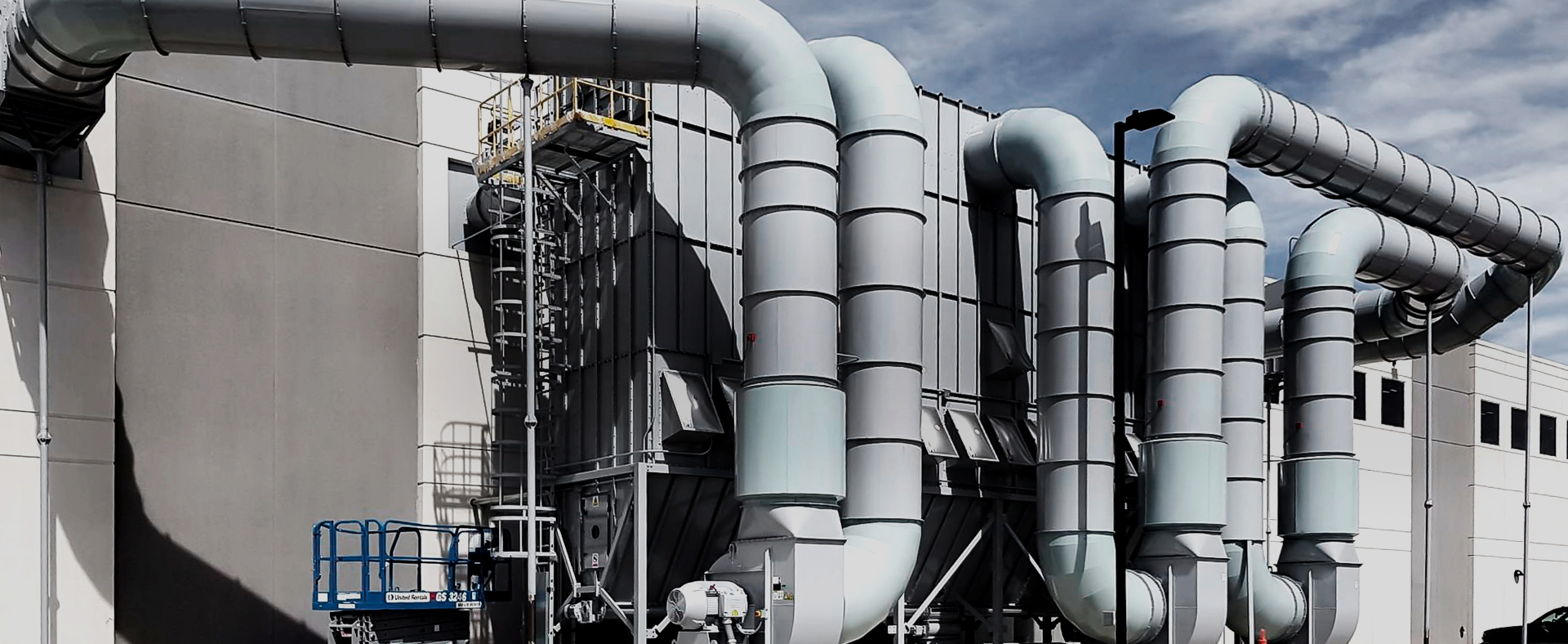
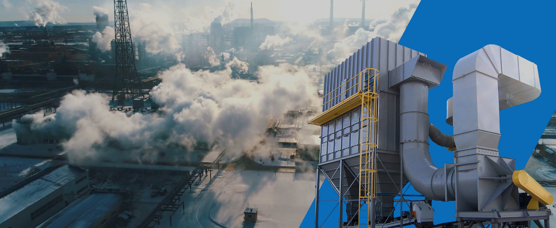

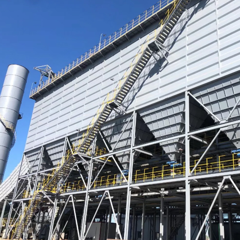
وصف المنتج/الغرض/الأشخاص المناسبين يتم استخدام كيس الفلتر لتصفية الغاز بحيث يفي الغاز بمعايير الانبعاثات. عندما يتراكم الغبار إلى حد معين على السطح الخارجي لكيس ا...
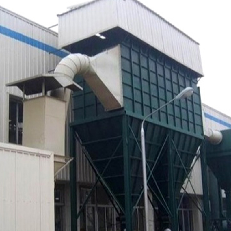
وصف المنتج/الغرض/الأشخاص المناسبين استخدم أكياس الفلتر لتصفية الغاز بحيث يفي الغاز بمعايير الانبعاثات. عندما يتراكم الغبار إلى حد معين على السطح الخارجي لكيس الفلتر وتصل...
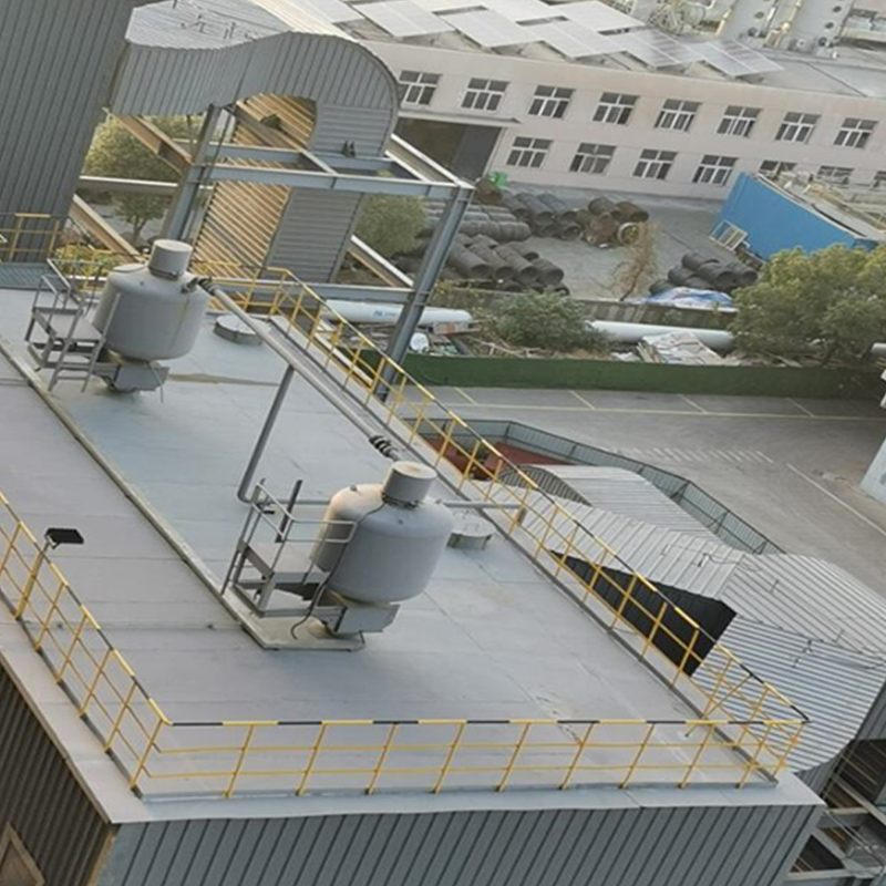
وصف المنتج/الغرض/الأشخاص المناسبين يتم ترتيب أكياس الفلتر في حلقة دائرية يكون فيها العمود الدوار هو المركز. يمكن ترتيب 20 حلقة كحد أقصى. العمود الدوار عبارة عن هيكل أسطو...
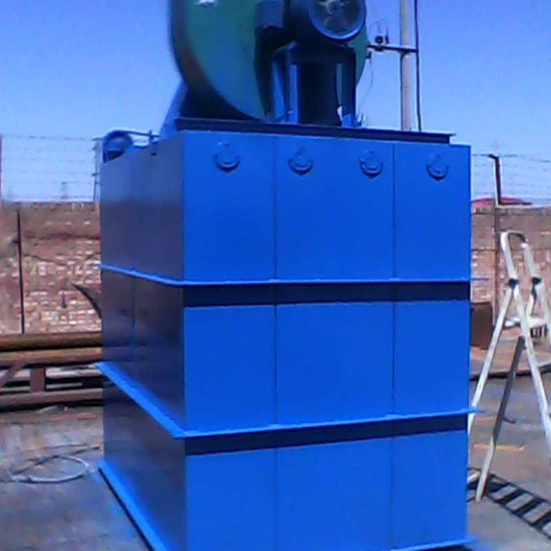
وصف المنتج/الغرض/الأشخاص المناسبين يتم استخدام كيس الفلتر لتصفية الغاز بحيث يفي الغاز بمعايير الانبعاثات. الجهاز مزود بجهاز اهتزاز ميكانيكي بعمود كامات لامركزي، والذي يت...
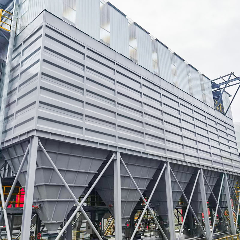
وصف المنتج/الغرض/الأشخاص المناسبين يتم استخدام خرطوشة الفلتر لتصفية الغاز بحيث يفي الغاز بمعايير الانبعاثات. عندما يتراكم الغبار إلى حد معين على السطح الخارجي لخرطوشة ال...
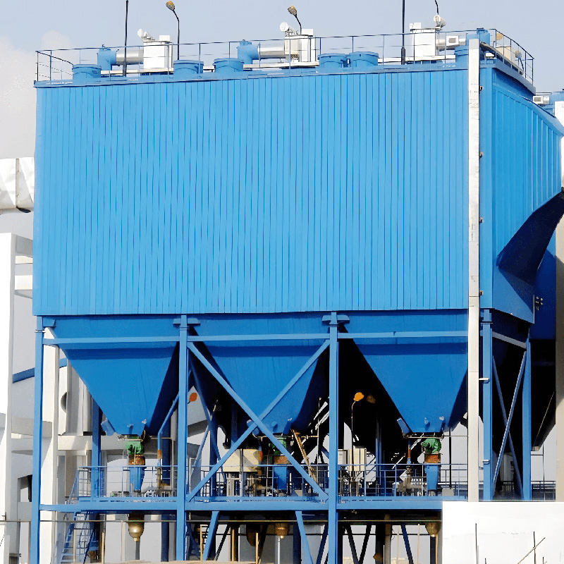
وصف المنتج/الغرض/الأشخاص المناسبين هذا النوع من معدات إزالة الغبار لديه نطاق معين من المتطلبات لمقاومة الغبار في الغاز، ويتطلب بشكل عام أن تكون مقاومة الغبار ضمن نطاق 10...
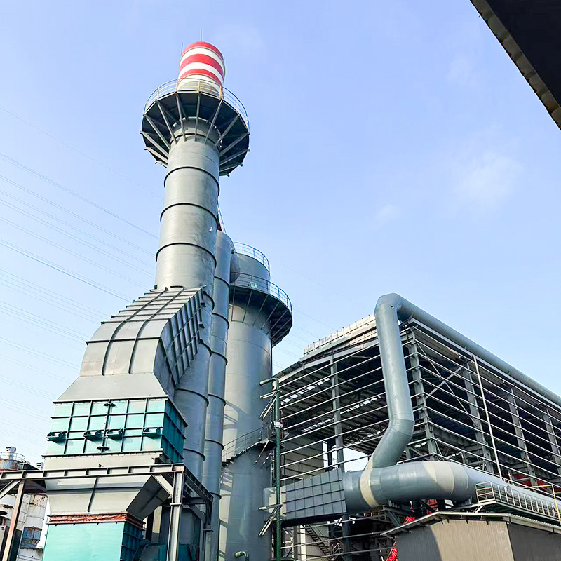
وصف المنتج/الغرض/الأشخاص المناسبين هذا النوع من مجمعات الغبار مناسب لمعالجة غاز المداخن المغبر الذي يحتوي على كمية كبيرة من بخار الماء. يدخل غاز المداخن الذي تم جمعه من ...
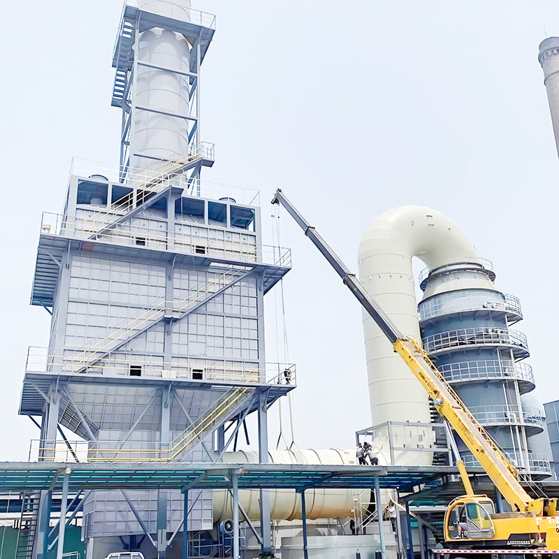
وصف المنتج/الغرض/الأشخاص المناسبين يتم استخدام هذا النوع من المنتجات بشكل عام كمعدات تكميلية لإزالة الغبار الناعم لإزالة الكبريت الرطب أو إزالة الغبار الرطب. يتم استخدام...
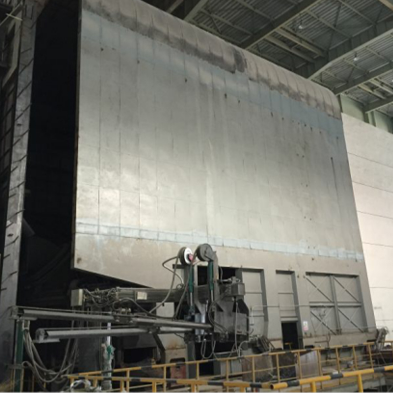
وصف المنتج/الغرض/الأشخاص المناسبين يشتمل غطاء المجموعة بشكل أساسي على غطاء متحرك وغطاء ثابت وعارضة مسار ومتاهة ومنفذ شفط ومحرك مشي وأجزاء أخرى. يمكن تقسيم غطاء الفرن ...
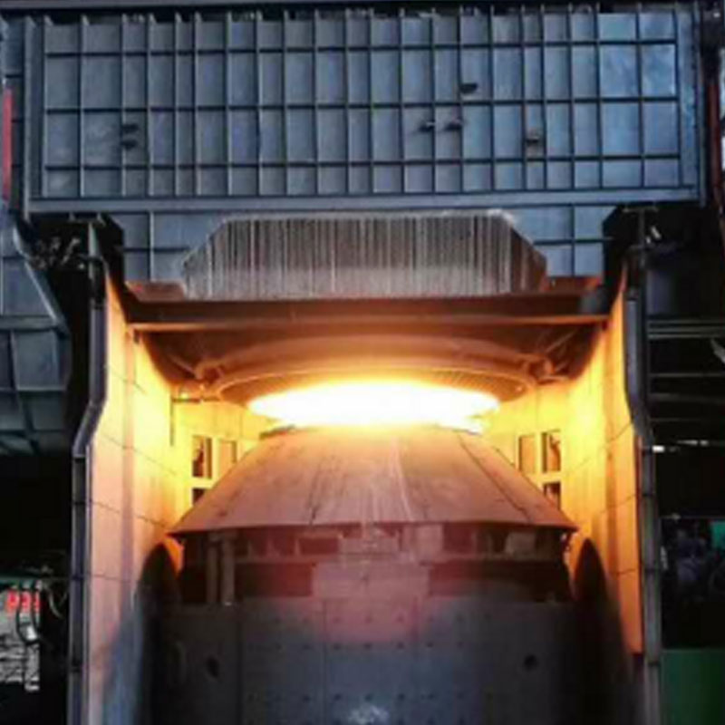
وصف المنتج/الغرض/الأشخاص المناسبين يتكون غطاء الالتقاط من عارضة دعم، وغطاء التقاط شفط على الوجهين، وحاجز، ومنفذ شفط. إن غطاء الالتقاط الأمامي لفرن المحول عبارة عن جها...
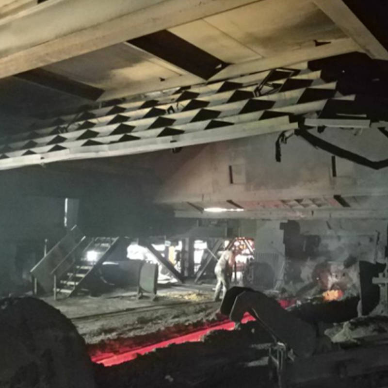
وصف المنتج/الغرض/الأشخاص المناسبين يتكون غطاء الالتقاط من غطاء مغلق بالكامل ومنفذ شفط داخلي وباب متحرك في الأعلى. إنه يجمع 95٪ من الدخان الناتج عندما ينقر الفرن العالي ع...
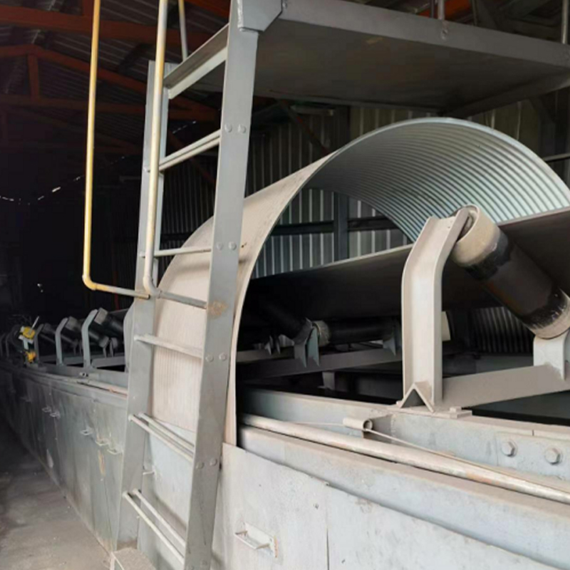
وصف المنتج/الغرض/الأشخاص المناسبين يتكون بشكل أساسي من هيكل الغطاء، وإطار جسم الغطاء، ووصلة جانبية ناعمة، وواجهات متصلة بكل منفذ تفريغ، وأنبوب تجميع. يمكن تعديله بسرع...
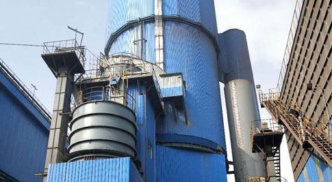 خريطة موقع Wuxi Xinsanzhou -
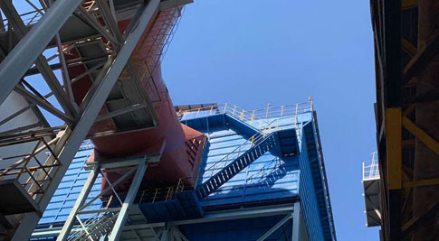 خريطة موقع مشروع Tianjin -
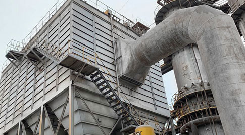 نقل جامع الغبار من فرن الجير في موقع مشروع Tangshan Donghua -
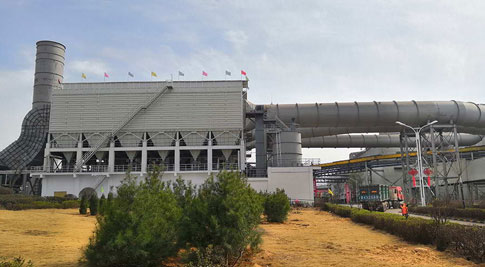 خريطة موقع مشروع Shanxi Xintai -
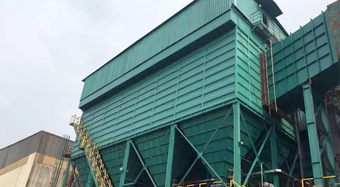 خريطة موقع مشروع Jiangyin Xingcheng -
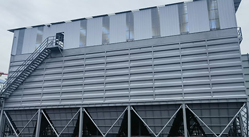 إزالة الغبار الثانوية لمحول الصلب Desheng -
إزالة الغبار الثانوية لمحول الصلب Desheng -
إزالة الغبار الثانوية لمحول الصلب Desheng -
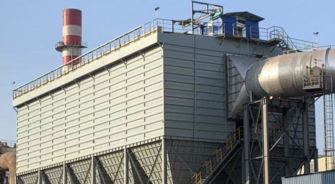 إزالة الغبار الثانوية لمحول صناعة الصلب في جيوان الحديد والصلب ، هنان -
إزالة الغبار الثانوية لمحول صناعة الصلب في جيوان الحديد والصلب ، هنان -
إزالة الغبار الثانوية لمحول صناعة الصلب في جيوان الحديد والصلب ، هنان -
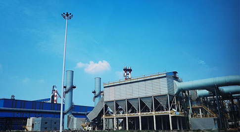 Zhongtian حقيبة الغبار جامع الغبار -
Zhongtian حقيبة الغبار جامع الغبار -
Zhongtian حقيبة الغبار جامع الغبار -
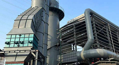 Fuzhou Wuhang إزالة الغبار الرطب -
A مخطط نظام جمع الغبار هو تمثيل مصغر لمسار تدفق الهواء من غطاء الالتقاط إلى وحدة التصفية والمروحة. ومن الناحية العملية، فهي أول أداة تشخيصية يقوم مهندس المصنع بفحصها عند ضعف أداء حجرة الأكياس، أو سدادات مجاري الهواء، أو تعثر محرك المروحة عند التحميل الزائد. لقد قمت ذات مرة بمراجعة رسم لمصنع أسمنت حيث يتطلب التصميم سرعة قناة تبلغ 18 م/ث، ولكن النظام المبني بالكاد يصل إلى 12 م/ث. استقر غبار الأسمنت الناعم في مسارات أفقية وتسبب في ارتفاع الضغط خلال ثلاثة أسابيع من بدء التشغيل. وكان هذا الفشل واضحًا بالفعل في الرسم التخطيطي قبل صب الأساس الأول. 18 م/ث سرعة التصميم مقابل سرعة المجال البالغة 12 م/ث هي نوع التناقض الذي يظهر في مراجعة الرسم قبل طلب المعدات. ما الذي يجب أن يتضمنه مخطط نظام جمع الغبار؟ يحتوي أي مخطط مفيد على ست كتل: نقاط الالتقاط، والأغطية، ومجاري الهواء، ووحدة التصفية، والمروحة، وتفريغ الغبار. فقدان واحد منهم يجعل الرسم عديم الفائدة للتشغيل. تحدد نقطة الالتقاط تدفق الهواء المطلوب. غطاء محرك السيارة يحدد سرعة الالتقاط. ينقل مجرى القناة الغبار بسرعة تحافظ على حركة الجزيئات. تقوم وحدة الفلتر بفصل الغبار عن الهواء. توفر المروحة الضغط الثابت للتغلب على مقاومة النظام. يؤدي تفريغ الغبار إلى إزالة المواد المجمعة بأمان. الكتل الأساسية لمخطط نظام جمع الغبار الصناعي ودورها التصميمي كتلة دور التصميم نقطة الالتقاط يحدد معدات العملية التي تحتاج إلى تدفق الهواء هود يحدد سرعة الالتقاط المطلوبة وحجم الهواء تشغيل القناة يحدد سرعة النقل وفقدان الضغط وحدة التصفية يضبط سرعة الترشيح ومنطقة التصفية مروحة يوفر ضغطًا ثابتًا للتغلب على مقاومة النظام تفريغ الغبار يتعامل مع المواد التي تم جمعها بأمان بالنسبة للغبار الجاف وغير المسترطب، أ جامع الغبار ذو كيس النبض النفاث ذو الضغط المنخفض غالبًا ما تكون وحدة التصفية المحددة لأنها توازن بين كفاءة الترشيح وطاقة التنظيف. جهاز تجميع الغبار النابض ذو الضغط المنخفض للتحكم في الغبار الناعم يستخدم حجرة الأكياس هذه التنظيف النفاث للغبار الجاف وغير المسترطب، مما يحقق انبعاثات أقل من 8 ملجم/نيوتن متر مكعب. إنها تناسب مختلف الصناعات ولكنها ليست ذات رطوبة عالية أو غبار لزج. عرض المنتج → سرعة الالتقاط ليست رقمًا عالميًا. وتتراوح من 0.5 م/ث للأبخرة الخفيفة إلى 2.5 م/ث للغبار الكاشط الثقيل، ويجب أن يوضح الرسم البياني القيمة المختارة لكل غطاء. قراءة تدفق الهواء والسرعة على مخطط نظام جمع الغبار يجب أن يوضح الرسم البياني الحجم بالمتر المكعب في الساعة والسرعة بالمتر في الثانية لكل فرع. السرعة هي ما يحافظ على تحرك الغبار عبر مجاري الهواء. 100 ملم قطر القناة 15 إلى 18 م/ث 150 ملم قطر القناة 18 إلى 22 م/ث 200 ملم قطر القناة 20 إلى 25 م/ث يرتبط الحجم والسرعة بمساحة المقطع العرضي. تنقل قناة قطرها 150 مم بسرعة 20 م/ث حوالي 1,270 مترًا مكعبًا في الساعة. وتنقل نفس القناة بسرعة 15 م/ث حوالي 950 مترًا مكعبًا في الساعة. يجب أن يوضح الرسم البياني هذا الحساب لكل فرع. 100 ملم 15 إلى 18 م/ث 150 ملم 18 إلى 22 م/ث 200 ملم 20 إلى 25 م/ث تتسبب سرعات مجاري الهواء غير المصممة والتي تقل عن 15 م/ث في المسارات الأفقية في ترسب الغبار وارتفاع ثابت في انخفاض الضغط. تحقق من كل فرع قبل قبول التصميم. الأخطاء الشائعة التي تظهر في الرسوم البيانية لنظام جمع الغبار النباتي يتم رسم الأخطاء الأكثر تكلفة قبل بدء البناء. إن مراجعة الرسم التخطيطي مقابل القائمة أدناه تكتشف تقريبًا كل فشل ميداني رأيته. قيم تدفق الهواء في الفرع مفقودة تعمل القناة الأفقية الطويلة بدون أبواب فحص يتم وضع موصلات مرنة على مدخل المروحة بدلاً من المخرج ضغط إمداد الهواء المضغوط أقل من 0.5 ميجا باسكال لتنظيف النفاث النبضي تم وضع الأغطية بعيدًا جدًا عن نقطة الانبعاث لا يوجد منحدر على المسارات الأفقية التي تحمل غبارًا كاشطًا ثقيلًا كل خطأ له أعراض ميدانية واضحة: فقدان قيم تدفق الهواء يجعل من المستحيل موازنة النظام؛ تعمل المسارات الأفقية الطويلة بدون أبواب الوصول على إنشاء انسداد مخفي؛ تنهار الموصلات المرنة الموجودة على جانب الشفط تحت الضغط السلبي؛ انخفاض ضغط الهواء المضغوط يترك الأكياس غير نظيفة؛ غطاء محرك السيارة بعيدًا جدًا عن المصدر يهدر الطاقة. يمكن أن يؤدي فحص بسيط لانخفاض الضغط عبر وحدة الفلتر إلى توفير أسابيع من استكشاف الأخطاء وإصلاحها. خطط لدورة تنظيف تبدأ عند 1500 باسكال والفحص اليدوي فوق 2000 باسكال. كيفية إنشاء مخطط نظام جمع الغبار الخاص بالموقع ابدأ بخطة أرضية متدرجة واعمل من كل غطاء إلى الوحدة. بالنسبة لأفران صناعة الصلب، تعد هندسة الغطاء هي العنصر الأول الحاسم، وهي عنصر أساسي فرن كهربائي بغطاء مغلق بالكامل يلتقط الأبخرة من المصدر مع تقليل متطلبات تدفق الهواء الإجمالية. غطاء فرن كهربائي مغلق بالكامل لالتقاط الدخان غطاء مغلق بالكامل يلتقط أكثر من 95% من الأبخرة المنبعثة من الأفران الكهربائية، ويقلل الضوضاء بمقدار 20-25 ديسيبل، ويتميز بمراقبة درجة الحرارة وتخفيف الانفجارات. عرض المنتج → قم بإدراج كل نقطة التقاط وقياس أبعاد العملية الفعلية. قم بتضمين فروق الارتفاع لأن الناهضات الرأسية تغير توازن الضغط. حساب تدفق الهواء المطلوب لكل غطاء محرك السيارة على أساس سرعة الالتقاط ومنطقة فتح غطاء محرك السيارة. اختر قطر قناة قياسي للحفاظ على السرعة ضمن نطاق النقل. حساب خسائر ضغط القنوات الفرعية والرئيسية، بما في ذلك الأكواع والخراطيم المرنة. حدد المروحة والمحرك بناءً على مقاومة النظام بالإضافة إلى هامش يتراوح من 10 إلى 15 بالمائة لتراكم كعكة الغبار. حدد ميلًا بنسبة 1 بالمائة أو أكثر للممرات الأفقية وقم بوضع أبواب التفتيش كل 3 إلى 4 أمتار. في القياسات الميدانية، إجمالي انخفاض ضغط النظام هو الضغط الثابت للمروحة عندما تعمل المروحة بالسرعة التصميمية دون أي تسرب. الرسم التخطيطي الذي لا يسمح لك بحساب هذه القيمة غير مكتمل. مطابقة المخطط لخصائص الغبار يحدد حجم الغبار ودرجة كشطه وسائط المرشح وسرعة القناة وهندسة الغطاء، لذلك لا يمكن تصميم المخطط بدون عينة من الغبار. جامعي الخرطوشة بصمة مدمجة، جيدة للغبار الجاف الناعم. سرعة الترشيح 0.8 إلى 1.2 م/دقيقة. استخدم جامع الغبار بخرطوشة مرشح النبض النفاث ذو الضغط المنخفض عندما تكون المساحة محدودة والغبار ليس كاشطًا. جامع الغبار بخرطوشة فلتر النبض النفاث ذو الضغط المنخفض مجمع خرطوشة مدمج للغبار الجاف الناعم، مع سرعة ترشيح أقل وتصميم موفر للمساحة. مناسب للغبار غير المسترطب عند درجات حرارة أقل من 150 درجة مئوية. عرض المنتج → جامعي الأكياس قوية ومناسبة للغبار الكاشطة والساخنة. سرعة الترشيح 1.0 إلى 2.5 م/دقيقة. يسمح تكوين الكيس بأكياس طويلة لمنطقة مرشح أكبر في مساحة أضيق. بالنسبة لغبار الكوارتز الكاشط، استخدم سرعة قناة أعلى من 20 م/ث وحقيبة مرشح ذات قاع معزز. يجب أن يُظهر الرسم التخطيطي أيضًا صندوق التسرب أو الإعصار قبل وحدة التصفية للجسيمات الثقيلة. لمزيد من التفاصيل حول كيفية أداء أنظمة الأكياس عبر الصناعات، راجع مقالتنا حول جامعي الغبار مرشح الأكياس كأوصياء على النقاء الصناعي . بالنسبة لغبار الكوارتز الكاشط، استخدم سرعة قناة أعلى من 20 م/ث وحقيبة مرشح ذات قاع معزز. الأسئلة المتداولة ما هو الرقم الأكثر أهمية في مخطط نظام جمع الغبار؟ سرعة الالتقاط في كل غطاء محرك السيارة. بالنسبة للغبار الذي يزيد حجم جسيماته عن 100 ميكرومتر، تكون سرعة الالتقاط بين 1.5 و2.5 م/ث نموذجية. لماذا يحتاج المخطط إلى خط هواء مضغوط منفصل؟ يتطلب التنظيف بالنفث النبضي الحد الأدنى من الضغط، عادة ما يتراوح بين 0.5 إلى 0.6 ميجا باسكال. إذا لم يحدد الرسم مصدر إمداد الهواء وقطر الرأس، فلن يتم تنظيف أكياس الفلتر بشكل صحيح. كيف أعرف ما إذا كان مخطط نظام جمع الغبار يفتقد شيئًا ما؟ تحقق من وجود ثلاث قيم: تدفق الهواء الفرعي، وسرعة القناة الرئيسية، والضغط الثابت للمروحة. في حالة غياب أي شخص، لا يمكن استخدام الرسم للتكليف. هل يجب علي استخدام خرطوشة أو مجمع أكياس للغبار الناعم؟ استخدم مجمع الخرطوشة للغبار الناعم والجاف وغير الكاشط مع سرعة ترشيح تتراوح من 0.8 إلى 1.2 م/دقيقة. اختر كيسًا للغبار الكاشطة أو الساخنة. تذكر: الرسم التخطيطي هو أداة قرار، وليس زخرفة. استخدمه للتحقق من سرعة الالتقاط وسرعة القناة والضغط الثابت للمروحة قبل تسجيل الخروج من النظام. .dust-collection-system-diagram { --accent: #146fb6; --text: #212121; font-family: 'Helvetica Neue', Arial, sans-serif; color: var(--text); font-size: 16px; line-height: 1.9; padding: 20px; counter-reset: section;}.dust-collection-system-diagram p { font-size:16px !important; margin-bottom:12px; }.dust-collection-system-diagram h2 { font-size:22px; font-weight:bold; text-align:left; margin-bottom:12px !important; margin-top:50px; padding-left:60px; position:relative; line-height:1.6; }.dust-collection-system-diagram h2:before { counter-increment: section; content: counter(section); position:absolute; top:-12px; left:0; font-size:64px; font-weight:bold; color: color-mix(in srgb, var(--accent) 18%, transparent); line-height:1.4; }.dust-collection-system-diagram h3 { font-size:16px; font-weight:bold; text-align:left; margin-bottom:12px; position:relative; padding-left:16px; }.dust-collection-system-diagram h3:before { content:''; position:absolute; left:0; top:6px; width:5px; height:14px; background:var(--accent); border-radius:2px; }.dust-collection-system-diagram ul { margin-bottom:12px; list-style-type:disc; list-style-position:inside; }.dust-collection-system-diagram ol { margin-bottom:12px; list-style-type:decimal; list-style-position:inside; padding-left:0; }.dust-collection-system-diagram li { list-style:inherit; font-size:16px; margin-bottom:6px; }.dust-collection-system-diagram th { font-weight:bold; border:1px solid #cccccc; padding:8px; }.dust-collection-system-diagram td { border:1px solid #cccccc; padding:8px; }.dust-collection-system-diagram caption { caption-side:bottom; font-size:16px; margin-bottom:12px; font-style:italic; color:#808080; }.dust-collection-system-diagram .article-section table { display: table !important; width:100%; border-collapse:collapse; margin-bottom:20px; }.dust-collection-system-diagram .article-section thead { display: table-header-group !important; }.dust-collection-system-diagram .article-section tbody { display: table-row-group !important; }.dust-collection-system-diagram .article-section tr { display: table-row !important; }.dust-collection-system-diagram .article-section th { display: table-cell !important; }.dust-collection-system-diagram .article-section td { display: table-cell !important; }.dust-collection-system-diagram tr:first-child td { background: var(--accent); color:#ffffff; font-weight:bold; }.dust-collection-system-diagram tr:nth-child(even) td { background: color-mix(in srgb, var(--accent) 5%, #ffffff); }.dust-collection-system-diagram td:first-child { font-weight:bold; background: color-mix(in srgb, var(--accent) 8%, #ffffff); }.dust-collection-system-diagram tr:first-child td:first-child { background: var(--accent); }.dust-collection-system-diagram .lead { font-size:18px !important; line-height:1.8; background: color-mix(in srgb, var(--accent) 6%, #ffffff); padding:20px; border-radius:10px; border-left:4px solid var(--accent); margin-bottom:24px; }.dust-collection-system-diagram .data-highlight { display:flex; align-items:center; gap:14px; background: color-mix(in srgb, var(--accent) 10%, #ffffff); border-bottom:6px solid var(--accent); border-radius:6px; padding:16px 20px; margin:24px 0; font-size:18px; line-height:1.8; }.dust-collection-system-diagram .highlight-number { font-size:32px; font-weight:bold; color: var(--accent); letter-spacing:-1px; line-height:1.4; }.dust-collection-system-diagram .definition-block { background:#ffffff; border:1px solid #e0e0e0; border-top:4px solid var(--accent); padding:20px; margin:24px 0; box-shadow:0 4px 12px rgba(0,0,0,0.05); border-radius:8px; }.dust-collection-system-diagram .callout-card { background: var(--accent); color:#ffffff; padding:20px; border-radius:8px; margin:24px 0; }.dust-collection-system-diagram .feature-list { list-style:none; padding-left:0; margin-bottom:12px; }.dust-collection-system-diagram .feature-list li { position:relative; padding-left:28px; margin-bottom:8px; }.dust-collection-system-diagram .feature-list li:before { content:''; position:absolute; left:0; top:10px; width:14px; height:14px; background:var(--accent); border-radius:3px; }.dust-collection-system-diagram .metric-cards { display:flex; gap:16px; margin:24px 0; }.dust-collection-system-diagram .metric-card { flex:1; background: color-mix(in srgb, var(--accent) 5%, #ffffff); border:1px solid #e0e0e0; border-radius:8px; padding:16px; text-align:center; }.dust-collection-system-diagram .metric-value { display:block; font-size:20px; font-weight:bold; color:var(--accent); line-height:1.6; }.dust-collection-system-diagram .metric-label { display:block; font-size:14px; line-height:2; color:#666666; }.dust-collection-system-diagram .metric-card strong { display:block; font-size:16px; line-height:1.9; }.dust-collection-system-diagram .range-chart { width:100%; background: color-mix(in srgb, var(--accent) 4%, #ffffff); border-radius:8px; padding:20px; margin:24px 0; box-sizing:border-box; }.dust-collection-system-diagram .chart-row { display:grid; grid-template-columns:80px 1fr 90px; align-items:center; gap:12px; margin-bottom:12px; }.dust-collection-system-diagram .chart-row:last-child { margin-bottom:0; }.dust-collection-system-diagram .chart-label { font-size:14px; line-height:2; font-weight:bold; color:var(--accent); }.dust-collection-system-diagram .chart-bar { background:#e6e6e6; border-radius:6px; height:28px; overflow:hidden; }.dust-collection-system-diagram .chart-fill { display:block; height:100%; background: var(--accent); border-radius:6px; }.dust-collection-system-diagram .chart-value { font-size:14px; line-height:2; text-align:right; color:#666666; }.dust-collection-system-diagram .compare-grid { display:grid; grid-template-columns:1fr 1fr; gap:20px; margin:24px 0; }.dust-collection-system-diagram .compare-col { background:#ffffff; border:1px solid #e0e0e0; border-radius:10px; padding:20px; }.dust-collection-system-diagram .compare-col h3 { color:var(--accent); border-bottom:2px solid var(--accent); padding-bottom:8px; margin-bottom:12px; }.dust-collection-system-diagram .steps { counter-reset: step; list-style:none; padding-left:0; }.dust-collection-system-diagram .steps li { position:relative; padding-left:52px; margin-bottom:14px; min-height:36px; }.dust-collection-system-diagram .steps li:before { counter-increment: step; content: counter(step); position:absolute; left:0; top:0; width:36px; height:36px; background:var(--accent); color:#ffffff; border-radius:50%; display:flex; align-items:center; justify-content:center; font-weight:bold; font-size:16px; }.dust-collection-system-diagram .steps li:not(:last-child):after { content:''; position:absolute; left:17px; top:36px; width:2px; height:calc(100% - 20px); background: color-mix(in srgb, var(--accent) 30%, transparent); }@media (max-width: 768px) { .dust-collection-system-diagram .metric-cards { flex-direction: column; } .dust-collection-system-diagram .compare-grid { grid-template-columns: 1fr; } .dust-collection-system-diagram .chart-row { grid-template-columns: 55px 1fr 70px; } .dust-collection-system-diagram h2 { font-size:20px; padding-left:44px; } .dust-collection-system-diagram h2:before { font-size:44px; top:-8px; }} .product-card{display:block;margin:20px 0;border:1px solid #e5e7eb;border-radius:10px;overflow:hidden;font-style:normal;background:#fff}.pc-inner{display:flex;text-decoration:none;color:inherit;align-items:center;min-height:120px}.pc-img{width:160px;min-width:160px;aspect-ratio:4/3;height:auto;min-height:120px;object-fit:cover;flex-shrink:0;display:block;align-self:stretch}.pc-body{padding:12px 16px;flex:1;min-width:0;display:flex;flex-direction:column;align-self:stretch;justify-content:center}.pc-title{display:block;font-size:15px;font-weight:600;color:#111;margin:0 0 6px;line-height:1.4}.pc-desc{display:-webkit-box;font-size:13px;color:#6b7280;margin:0 0 8px;line-height:1.5;overflow:hidden;-webkit-line-clamp:2;line-clamp:2;-webkit-box-orient:vertical}.pc-cta{display:block;font-size:13px;font-weight:600;color:#146FB6;margin-top:auto}.pc-inner:hover .pc-title{text-decoration:underline} .article-section a:not(.pc-inner),article a:not(.pc-inner){color:#146FB6}.pc-cta{color:#146FB6!important}
اقرأ المزيد
لماذا يعتبر جمع الغبار من النبات بأكمله مشكلة في النظام، وليس مشكلة في الصندوق عندما يخطط مصنع للصلب أو الأسمنت لإجراء ترقية كبيرة للتحكم في الغبار، فإن السؤال الأول عادة ما يكون حول المجمع نفسه. بعد أداء المركزي جامع الغبار يعتمد الأمر بشكل أكبر على كيفية مطابقة النظام بأكمله: حجم تدفق الهواء، وتوازن مجاري الهواء، وتصريف الرماد ونقله. لا يمكن للمسكن المبني جيدًا أن يعوض عن شبكة مجاري الهواء غير المتوازنة. تعمل المجمعات ذات الوحدة الواحدة التي تخدم آلة واحدة بشكل مختلف عن الأنظمة المركزية التي تخدم أغطية أو أفران أو ناقلات متعددة. في مشروع المصنع بأكمله، تتمتع كل قناة فرعية بمظهر مقاومة، ويجب أن يتلقى كل غطاء حصته المصممة من تدفق الهواء. إذا لم يتم حساب هذه الأرقام معًا، فسيتم حرمان بعض النقاط من الشفط بينما سيتم تحميل نقاط أخرى بشكل زائد، والنتيجة هي هروب الغبار من أضعف نقطة التقاط. المبدأ الأساسي تعامل مع المجمع والمروحة ومجاري الهواء ومعالجة الرماد كتصميم واحد متكامل. كل عنصر يضع حدودا للآخرين. العناصر الأساسية للتصميم المركزي يتم حساب إجمالي تدفق الهواء من مجموع جميع نقاط الالتقاط بهامش أمان قنوات فرعية متوازنة ذات حجم مناسب للسرعات المستهدفة لمنع استقرار الغبار يتوافق معدل تفريغ الرماد مع سعة قادوس التجميع منطق التحكم الذي يضبط تردد التنظيف حسب حمل الغبار الفعلي نبض نفاث أو هواء عكسي: مطابقة طريقة التنظيف لظروف المعالجة تعد طريقة التنظيف واحدة من أكثر الاختيارات أهمية في الأكياس الكبيرة. تعمل تصميمات النفاث النبضي والهواء العكسي على إزالة كتلة الغبار من أكياس الفلتر، ولكنها تناسب أوضاع تشغيل مختلفة. مقارنة طرق التنظيف الشائعة عامل نبض جيت عكس الهواء التسامح مع تحميل الغبار عالية، وتناسب أحمال الغبار الكثيفة معتدل، ويناسب الأحمال الخاضعة للرقابة البصمة السكن المدمجة وأقصر تصميم أكبر ومتعدد الأقسام كثافة التنظيف نبضات قوية وقصيرة المدة تدفق عكسي لطيف ومنخفض الضغط تطبيق نموذجي الأفران الكهربائية، تلبيد، أفران الجير عادم الفرن المستمر ذو الحجم الكبير طريقة المطابقة لعملية حقيقية في عادم الفرن الكهربائي الفولاذي، يمكن أن يرتفع تحميل الدخان بشكل حاد أثناء الشحن والنقر. يتعامل التصميم النفاث النبضي مع هذه الزيادات لأن كل نبضة تزيل الكعكة بسرعة، مما يحافظ على استقرار انخفاض الضغط. قد يتناسب عادم فرن الأسمنت الذي يعمل بشكل مستمر بكميات كبيرة مع محتوى غبار معتدل مع الهواء العكسي، مما يسمح بإخراج الأجزاء الفردية دون انقطاع دون مقاطعة التدفق. يجب أن تتبع طريقة التنظيف نمط حمل الغبار، وليس العكس. اسأل ما إذا كانت عمليتك تنتج غبارًا ثابتًا أو شائكًا قبل الاختيار. الإسكان والهيكل الصلب وتصميم القنوات الكبيرة بالنسبة للمنشآت الكبيرة، تعتبر الموثوقية الهيكلية مهمة بقدر أهمية الترشيح. يمكن للمبيت الذي يتشوه تحت الرياح أو الثلج أو الرماد المتراكم أن يؤدي إلى تشقق الدرزات واختلال الأبواب والسماح للغبار بتجاوز الأكياس. فحوصات التصميم التي تحمي التشغيل على المدى الطويل تم التحقق من أحمال الرياح والثلوج مقابل المنطقة المناخية المحلية يتم حساب حمل الرماد على جدران القادوس والدعامات في حالة انسداد التفريغ الكامل في أسوأ الحالات السكن مجزأ بحيث يمكن عزل قسم واحد للصيانة حماية من التآكل عند المرفقين والقطع الانتقالية على القنوات ذات القطر الكبير الخبرة الميدانية في عملية تحديث فرن الجير حيث كانت المساحة الأرضية محدودة، قمنا بتكديس صفين من الأقسام على ارتفاعات متداخلة. يكلف الإطار الفولاذي أكثر من التصميم القياسي، لكنه تجنب إيقاف التشغيل لاحقًا لإضافة السعة. ومن الناحية العملية، عادةً ما يتم استرداد التكلفة الهيكلية الإضافية خلال دورة الصيانة الرئيسية الأولى. نظام التنظيف وأكياس التصفية: التكاليف الخفية التي تحدد حجم الإنفاق خلال دورة الحياة سعر المعدات ليس سوى جزء من الصورة المالية. على مدى خمس إلى عشر سنوات، غالبًا ما تحدد كفاءة نظام التنظيف وعمر الأكياس التكلفة الإجمالية أكثر من عرض الأسعار الأولي. حيث تختبئ تكاليف التشغيل الصمامات النبضية التي تتسرب أو تفتح ببطء تهدر الهواء المضغوط في كل دورة تحتاج الحقائب التي تعمى مبكرًا أو تحترق بسبب الرحلات الحرارية إلى استبدال مبكر يؤدي التحكم السيئ في التنظيف إلى دورات تنظيف زائدة وارتداء الأكياس بشكل أسرع يؤدي نقل الرماد ذو الحجم الصغير إلى تراكم القادوس والتوقف القسري أسئلة يجب طرحها على الموردين قبل التوقيع سؤال كيف تبدو الإجابة الجيدة ما هي نسبة الهواء إلى القماش في التصميم؟ قيمة محددة يتم تبريرها حسب نوع الغبار ودرجة الحرارة كيف يتم تقدير استهلاك الهواء المضغوط؟ بناءً على عدد الصمامات ومدة النبض وتردد الدورة ما هو العمر المتوقع للحقيبة في ظل ظروفك؟ نطاق مرتبط بدرجة الحرارة والكيمياء وإعدادات التنظيف أدلة الحالة: المشكلة والتكوين والنتائج تعد بيانات المشروع الحقيقية أوضح طريقة للحكم على ما إذا كان تصميم النظام سيعمل أم لا. يصف الملخص التالي مشروع الأبخرة الثانوية النموذجية لمصنع الصلب. ترقية الأبخرة الثانوية لمصنع الصلب المشكلة الأصلية: أظهر المجمع الحالي انبعاثات عالية للمداخن وانخفاضًا متزايدًا في الضغط، مما تسبب في إطلاق إنذارات متكررة للمروحة أثناء ذروة الإنتاج. التكوين: نظام نفاث نبضي مركزي مع مساحة مرشح إجمالية مصممة لنسبة الهواء إلى القماش ضمن النطاق الطبيعي للغبار المعدني الناعم، مع منطقة منفصلة لدرجة الحرارة العالية للغطاء الأكثر سخونة. النتائج: بقي تركيز الغبار عند المخرج أقل من 10 مجم/م3، واستقر انخفاض الضغط عند حوالي 1200 باسكال أثناء التشغيل الثابت. درس التثبيت أثناء التشغيل، أظهرت إحدى القنوات الفرعية تدفقًا غير متساوٍ بسبب وضع الكوع بالقرب من مدخل المروحة. أدت إضافة مسار مستقيم للقناة أمام المروحة وتنعيم نصف قطر الكوع إلى تصحيح عدم التوازن. هذا تذكير بأن التحقق الميداني من تخطيط مجاري الهواء لا يقل أهمية عن الرسم. كيفية طلب تخطيط وسعر المصنع بالكامل يبدأ الاقتباس المفيد ببيانات عملية دقيقة. وبدون تدفق الهواء ودرجة الحرارة وخصائص الغبار وأبعاد الموقع، فإن أي سعر هو مجرد تقدير. معلومات للتحضير إجمالي حجم تدفق الهواء وعدد نقاط الالتقاط نطاق درجة حرارة الغاز، بما في ذلك ظروف الذروة وبدء التشغيل نوع الغبار وخصائص الجسيمات ومحتوى الرطوبة مساحة الموقع المتاحة وحدود الارتفاع قم بإرسال هذه المعلمات واطلب رسم تخطيطي أولي وتوصية بالاختيار لمصنعك. يمكن للدعم الهندسي تقييم شبكة مجاري الهواء وطريقة التنظيف والترتيب الهيكلي معًا. الأسئلة المتداولة س1: ما هي سرعة الفلتر التي يجب استخدامها في غرفة تخزين كبيرة؟ تعتمد سرعة الفلتر، أو نسبة الهواء إلى القماش، على نوع الغبار ودرجة الحرارة وطريقة التنظيف. يتطلب الغبار المعدني الناعم عادةً نسبة أقل من المواد الخشنة، ويجب أن تأتي القيمة النهائية من اختبار العملية والمراجعة الهندسية. س 2: كم من الوقت يستغرق تسليم نظام جمع الغبار للمصنع بالكامل؟ يختلف وقت التسليم باختلاف حجم النظام والمتطلبات الهيكلية المخصصة وجاهزية الموقع. تتضمن المشاريع الكبيرة عادة مراحل منفصلة للهندسة والتصنيع والتركيب والتشغيل، لذلك يجب تأكيد الجدول الزمني مقابل خطة المشروع التفصيلية. س3: ما أهمية تصميم مجاري الهواء في النظام المركزي؟ تتسبب القنوات غير المتوازنة في فقدان بعض الأغطية لكفاءة الالتقاط بينما يقوم البعض الآخر بسحب الهواء الزائد. الحجم والتخطيط المناسبان يحافظان على توزيع تدفق الهواء كما هو مصمم عبر جميع نقاط الالتقاط. .section-block { margin-bottom: 40px; font-family: 'Segoe UI', Roboto, 'Helvetica Neue', sans-serif; font-weight: 400; line-height: 2; } .section-block h2 { font-size: 20px; font-weight: 700; text-align: left; margin-bottom: 10px; padding-bottom: 6px; background: linear-gradient(90deg, #146fb6, #7fb8e6 60%, transparent); background-size: 100% 3px; background-repeat: no-repeat; background-position: bottom left; } .section-block h3 { font-size: 18px; font-weight: 700; text-align: left; margin-top: 5px; margin-bottom: 5px; color: #146fb6; } .section-block h4 { font-size: 16px; font-weight: 500; text-align: left; } .section-block p { margin-bottom: 5px; font-size: 16px; } .section-block ul, .section-block ol { margin-top: 8px; margin-bottom: 8px; padding-left: 20px; } .section-block li { list-style-position: inside; font-size: 16px; } .section-block ul li { list-style-type: disc; } .section-block ol li { list-style-type: decimal; } .section-block strong { font-weight: 500; } .section-block a { color: #146fb6; text-decoration: none; border-bottom: 1px dashed #146fb6; } .section-block .compare-table { width: 100%; border-collapse: separate; border-spacing: 0; border-radius: 8px; overflow: hidden; box-shadow: 0 2px 8px rgba(20, 111, 182, 0.12); margin: 12px 0; } .section-block .compare-table th { background: #146fb6; color: #ffffff; text-align: center; font-size: 16px; padding: 10px; font-weight: 500; } .section-block .compare-table td { text-align: center; font-size: 16px; padding: 10px; background: #f4f9fd; border-top: 1px solid #d6e8f5; } .section-block .compare-table tr:nth-child(even) td { background: #ffffff; } .section-block .callout-box { background: #eef6fc; border-left: 5px solid #146fb6; border-radius: 6px; padding: 12px 16px; margin: 14px 0; } .section-block .callout-box h4 { color: #146fb6; } .section-block .highlight-quote { background: linear-gradient(135deg, #146fb6 0%, #3a92d6 100%); color: #ffffff; border-radius: 10px; padding: 14px 18px; margin: 14px 0; } .section-block .highlight-quote p { color: #ffffff; margin: 0; } .section-block .field-note { background: #fff8ec; border: 1px solid #f2d9a6; border-radius: 8px; padding: 12px 16px; margin: 14px 0; } .section-block .field-note h4 { color: #b06b00; } .section-block .case-card { background: #ffffff; border: 1px solid #d6e8f5; border-top: 4px solid #146fb6; border-radius: 10px; box-shadow: 0 4px 14px rgba(20, 111, 182, 0.10); padding: 16px 20px; margin: 14px 0; } .section-block .case-card h3 { margin-top: 0; } .section-block .cta-box { background: #146fb6; color: #ffffff; border-radius: 10px; padding: 16px 20px; margin-top: 14px; } .section-block .cta-box p { color: #ffffff; margin: 0; } .section-block.faq-block h4 { background: #eef6fc; border-left: 4px solid #146fb6; padding: 8px 12px; border-radius: 4px; margin: 10px 0 0 0; } .section-block.faq-block p { background: #fafcfe; border: 1px solid #e3eef8; border-top: none; padding: 10px 14px; margin: 0 0 8px 0; border-radius: 0 0 4px 4px; }
اقرأ المزيد
تنتج معالجة خبث الفولاذ تحديًا يختلف بشكل حاد عن معظم تيارات الغبار الصناعية. أثناء عمليات التبريد الساخن، والصب، وحفر الخبث، لا يكون الغاز المنبعث سحابة جافة من الجسيمات. وهو عبارة عن بخار ساخن ورطب يحمل مسحوقًا ناعمًا ولزجًا يمكن أن يلتصق بالأسطح ويتصلب بمرور الوقت ويتفاعل مع المكثفات الحمضية. أ جامع الغبار الرطب قد يكون الأداء المصمم للاستخدام الصناعي العام جيدًا على الورق ولكنه يواجه صعوبة في غضون أشهر عند تعرضه لهذه الظروف. إن فهم السبب يتطلب النظر إلى فيزياء التيار، والتصميم الداخلي لبرج التنقية، ونظام المياه الذي يحافظ على تشغيل كل شيء. يتناول هذا الدليل اعتبارات التصميم الأكثر أهمية عند اختيار جهاز غسيل مبلل لخدمة الخبث الصلب. وهو يشرح كيفية تصرف الغبار، ومكان تركيب جهاز الغسيل في خط المعالجة، وأولويات التصميم التي تفصل المعدات الموثوقة عن المعدات التي بها مشكلات، وكيفية تقييم النظام قبل الالتزام به. ما الذي يجعل غبار خبث الفولاذ مختلفًا عن الغبار الصناعي العادي؟ عادةً ما تتعامل مهام التحكم في الغبار العادية مع الجزيئات الجافة التي تظل معلقة في الهواء ويمكن التقاطها من خلال الترشيح أو الأعاصير أو رذاذ الماء البسيط. يتصرف خبث الفولاذ بشكل مختلف لثلاثة أسباب رئيسية، ويؤثر كل منها على كيفية بناء مجمع الغبار الرطب. العامل 01 رطوبة عالية والتصاق يتلامس ماء التبريد مع الخبث المنصهر ويولد عمودًا كثيفًا من البخار محملاً بالجزيئات الدقيقة. غالبًا ما تكون هذه الجسيمات استرطابية ويمكن أن تشكل طبقة تشبه المعجون على الأسطح الباردة، والتي تجف بعد ذلك وتتصلب وتتحول إلى قشور. العامل 02 المكثفات الحمضية تذوب الغازات الحاملة للكبريت في رطوبة مكثفة وتشكل أغشية سائلة حمضية. تهاجم هذه الأفلام الفولاذ الكربوني ويمكن أن تسرع من تآكل المكونات الداخلية، خاصة عندما يتجمع السائل أو يجري ببطء. العامل 03 تشديد حدود الانبعاثات تواجه المنشآت المعدنية ضغوطًا متزايدة لتقليل انبعاثات الجسيمات. تستمر أهداف تركيز المخرج في الانخفاض، مما يعني أن جهاز الغسيل يجب أن يلتقط الجزيئات الدقيقة بشكل موثوق بدلاً من الاعتماد على الفصل الخشن وحده. في خدمة الخبث، لا يقوم جهاز الغسيل بإزالة الغبار فقط. إنها تدير تيارًا يحاول بنشاط بناء رواسب على جدرانه. مكان وضع جهاز الغسيل الرطب في خط معالجة خبث الفولاذ يساعد فهم المسار الكامل للغاز المنبعث في توضيح سبب أهمية كل مرحلة من مراحل جهاز الغسيل. يقوم خط معالجة الخبث النموذجي بترتيب المعدات في تسلسل حيث يعتمد كل من الالتقاط والنقل والتنظيف واستعادة المياه على بعضها البعض. حفرة الخبث إخماد والقبض مجاري الهواء والمروحة نقل البخار الغسيل الرطب مرحلة الرش القضاء على الضباب التنظيف العميق العادم النظيف الإصدار المتوافق مياه الغسيل المعاد تدويرها لتسوية ونزح الحمأة يقوم غطاء التجميع الموجود فوق حفرة الخبث بالتقاط البخار المتصاعد قبل أن ينتشر إلى داخل المبنى. تقوم القناة ومروحة السحب المستحثة بعد ذلك بنقل التيار إلى جهاز غسيل مبلل ، يوصف أحيانًا بأنه برج إزالة الغبار من النوع الرطب في وثائق صناعة الصلب. داخل البرج، تعمل مرحلة الرش على ترطيب الجزء الأكبر من الغبار والتقاطه، ويقوم مزيل الضباب بإزالة القطرات المحبوسة، وتتعامل مرحلة التنظيف الأعمق مع أدق الجزيئات قبل إطلاقها. التسلسل مهم لأن كل مرحلة تعتمد على التي تسبقها. إذا كان غطاء الالتقاط يسحب القليل جدًا من الهواء، فسيهرب البخار إلى مساحة العمل. إذا كانت القناة ذات انحدار ضعيف أو لا يوجد تصريف، فإن المكثفات تتجمع وتمنع التدفق. غالبًا ما تظهر مشكلات المنبع هذه لاحقًا كمشكلات في جهاز الغسيل، ولهذا السبب أ جهاز تنظيف الغبار الرطب يجب دائمًا تقييمها كجزء من السطر بأكمله. ثلاث أولويات تصميمية لجهاز تنظيف الغبار الرطب في خدمة الخبث يعتمد الأداء الموثوق في تطبيقات الخبث على ثلاث أولويات للتصميم. يعالج كل منها وضع فشل مختلفًا، ويميل الضعف في أي منها إلى تقصير عمر المعدات أو دفع الانبعاثات إلى ما هو أبعد من الهدف. 1. مقاومة الحشف والالتصاق باعتبارها ساحة المعركة الأولى يعد تكوين القشور على جدران البرج والمكونات الداخلية هو أكثر حالات الفشل شيوعًا في أجهزة تنقية الغاز الرطبة المعدنية. بمجرد أن تبدأ الطبقة في التشكل، فإنها تضيق مسار التدفق، وتعطل أنماط الرش، وتخلق أسطحًا جديدة لمزيد من الترسيب. تعالج أساليب التصميم النموذجية هذا الأمر من خلال عدة تدابير تعمل معًا. الأساليب الشائعة لمكافحة الحشف طبقة غاز أو طبقات ترطيب الجدار التي تمنع الغبار من الالتصاق مباشرة بسطح البرج. تخطيطات رش واسعة الممر تقلل من خطر انسداد الفوهة بسبب الجزيئات الصلبة. هندسة داخلية غير موحدة تتجنب المناطق الراكدة حيث يمكن أن تتراكم الرواسب. منافذ الفحص والتنظيف التي يمكن الوصول إليها والموجودة في نقاط الترسيب المعروفة. 2. التقاط الجسيمات الدقيقة وإزالة الضباب الجزء الدقيق من بخار الخبث هو الجزء الأكثر صعوبة في التحكم في التيار. من السهل نسبياً تبليل وتجميع الجسيمات الخشنة، ولكن المواد التي تقل عن الميكرون أو القريبة من الميكرون يمكن أن تنزلق خلال مرحلة رش بسيطة. يتطلب تحقيق جودة منفذ متسقة اتباع نهج متعدد الطبقات. المرحلة الوظيفة الأساسية التركيز على التصميم النموذجي مرحلة الرش ترطيب الغبار بالجملة والتقاطه تغطية الفوهة وحجم القطرة التقاط محسّن اصطدام الجسيمات الدقيقة والتقاطها فوهتان لتذرية السوائل للحصول على قطرات أنعم القضاء على الضباب إزالة القطرات المحبوسة مزيل ماء عالي الكفاءة مع الصرف تولد فوهات رذاذ السائلين قطرات دقيقة تزيد من احتمالية التلامس مع الجزيئات الدقيقة. ثم يقوم مزيل الضباب عالي الكفاءة بإزالة القطرات التي تحمل الغبار خارج البرج. بدون هذه الخطوة الأخيرة، قد يلتقط جهاز الغسيل الغبار داخليًا مع استمرار إطلاقه من خلال الرطوبة المحمولة. 3. اختيار المواد ضد المكثفات الحمضية تجمع خدمة الخبث بين تحديين ماديين: المكثفات المسببة للتآكل والمواد الصلبة الدقيقة الكاشطة. قد تستمر المواد التي تقاوم الهجوم الحمضي في التآكل عند الاتصال المستمر بالجسيمات، وقد تتآكل المواد التي تقاوم التآكل. تتضمن خيارات المواد النموذجية لأجهزة الغسيل الرطب المعدنية ما يلي. مركب FRP يوفر البناء المقوى بالألياف الزجاجية مقاومة قوية للتآكل بتكلفة معتدلة، ومناسب للمناطق ذات درجات الحرارة المنخفضة. دوبلكس ستانلس ستيل إن القوة والمقاومة العالية لكل من الكلوريد والهجوم الحمضي تجعله خيارًا شائعًا للمناطق الرطبة الصعبة. بطانة واقية يمكن للبطانات المقاومة للتآكل المطبقة على أغلفة الفولاذ الكربوني أن تطيل عمر الخدمة حيث يتداخل التعرض للتآكل والحمض. تداول المياه والتعامل مع الحمأة: نصف النظام الذي غالبًا ما يتم التغاضي عنه يكون جهاز الغسيل الرطب مستقرًا مثل نظام المياه الموجود خلفه. تحمل مياه الغسيل المتداولة الغبار الملتقط، وإذا لم تتم إزالة هذه المادة بشكل مستمر، يصبح الماء سميكًا وكاشطًا وعرضة للتقشير. والنتيجة هي انخفاض كفاءة الرش، وصيانة الفوهة بشكل متكرر، وأداء المخرج غير المستقر. تسوية يتم فصل المواد الصلبة عن ماء الغسيل في خزان الترسيب قبل إعادة التدوير. إعادة التدوير تعود المياه النقية إلى رؤوس الرش، مما يقلل الطلب على المياه العذبة. نزح المياه يتم ضغط الحمأة في كعكة صلبة للتعامل معها والتخلص منها. تتعامل العديد من المرافق مع هدف تصريف مياه الصرف الصحي الخارجي بالقرب من الصفر كهدف على مستوى النظام وليس سمة لأي برج منفرد. ويعتمد تحقيق ذلك على قدرة الترسيب، وحجم مضخة التدوير، ومعدات نزح المياه التي تعمل معًا. عندما يكون حجم أي عنصر صغيرًا، يمتص جهاز غسل الغاز العواقب من خلال انخفاض الكفاءة وزيادة خطر الانسداد. اختيار جهاز الغسيل الرطب المناسب لخبث الفولاذ: قائمة مرجعية عملية يكون اختيار المعدات لخدمة الخبث أسهل عندما يتبع التقييم مجموعة منظمة من الأسئلة. تغطي قائمة المراجعة التالية النقاط التي غالبًا ما تفصل بين عمليات التثبيت الناجحة وعمليات التثبيت المتعثرة. هل تم قياس محتوى رطوبة المدخل والتصاق الغبار في ظل ظروف تشغيل حقيقية بدلاً من افتراضها من قيم التصميم؟ هل يشتمل البرج على ميزات داخلية مخصصة خصيصًا للحد من التصاق الغبار بالجدران والمكونات؟ هل تتوافق مرحلة إزالة الضباب مع نطاق حجم الجسيمات الذي يجب التحكم فيه لتحقيق هدف المنفذ؟ هل يشتمل نظام تدوير المياه على الترسيب الكافي، وقدرة الضخ، ونزح المياه من الحمأة من أجل التشغيل المستمر؟ هل تم اختيار مواد البناء لتحمل المكثفات الحمضية والمواد الصلبة الناعمة الكاشطة؟ إذا كانت أي من هذه المناطق مفقودة أو غير محددة، فإن مجمع الغبار الرطب الذي يبدو مناسبًا في ورقة المواصفات قد يواجه الانسداد أو التآكل أو انحراف الانبعاثات خلال فترة قصيرة من التشغيل في خدمة خبث الفولاذ. الأسئلة المتداولة س 1: هل يمكن لجهاز الغسيل الرطب القياسي التعامل مع بخار خبث الفولاذ بشكل فعال؟ قد تعمل الوحدة ذات الأغراض العامة لفترة من الوقت، ولكن بدون ميزات داخلية مصممة لمقاومة الترسبات اللزجة، فإن خطر التلوث يرتفع بسرعة. تستفيد تطبيقات الخبث عادةً من هندسة البرج وترتيبات الرش المختارة خصيصًا للغبار الرطب اللاصق. س2: ما هو أداء الانبعاثات الذي يمكن أن يحققه جهاز الغسيل الرطب في معالجة الخبث؟ يمكن لنظام متعدد المراحل مع تعزيز التقاط الرذاذ وإزالة الضباب بكفاءة عالية أن يلبي أهداف الجسيمات الصارمة بشكل متزايد المستخدمة في العمليات المعدنية. ويعتمد الأداء النهائي على ظروف الدخول وخصائص الغبار وكيفية تكوين النظام بالكامل وصيانته. س3: كيف تتم إدارة مياه الغسيل في هذه الأنظمة؟ عادةً ما يتم توجيه مياه الغسيل من خلال الترسيب وإعادة التدوير ونزح المياه من الحمأة. وهذا يسمح بإعادة استخدام معظم المياه في مرحلة الرش بينما تتم إزالة المواد الصلبة المحتجزة ككعكة يمكن التحكم فيها للتخلص منها. س 4: لماذا تعتبر اختيارات المواد مهمة جدًا بالنسبة لأجهزة تنقية الخبث؟ تهاجم المكثفات الحمضية والمواد الصلبة الدقيقة الكاشطة المعدات بطرق مختلفة. يساعد اختيار المواد التي تعالج كلا التهديدين على منع التآكل والتآكل المبكر، وهما من بين الأسباب الأكثر شيوعًا للاستبدال المبكر. .slag-article { font-family: 'Segoe UI', Roboto, 'Helvetica Neue', sans-serif; font-weight: 400; line-height: 2; color: #1d2d3d;}.slag-article section,.slag-article.section-block { margin-bottom: 40px;}.slag-article .section-block { margin-bottom: 40px; padding: 24px 28px; background: #ffffff; border-radius: 16px; box-shadow: 0 6px 24px rgba(20, 111, 182, 0.08); border: 1px solid #e3edf6;}.slag-article .section-block h2 { font-size: 20px; font-weight: 700; text-align: left; margin-bottom: 10px; color: #0f3d61; padding-bottom: 8px; background-image: linear-gradient(90deg, #146fb6, #7ab8e6 60%, transparent); background-size: 100% 3px; background-repeat: no-repeat; background-position: left bottom;}.slag-article .section-block h3 { font-size: 18px; font-weight: 700; text-align: left; margin-top: 5px; margin-bottom: 5px; color: #146fb6; padding-left: 14px; border-left: 4px solid #146fb6;}.slag-article .section-block h4 { font-size: 16px; font-weight: 500; text-align: left; color: #0f3d61;}.slag-article .section-block p { font-size: 16px; margin-bottom: 5px;}.slag-article .section-block strong { font-weight: 500; font-size: inherit; color: #0f3d61;}.slag-article .section-block ul,.slag-article .section-block ol { margin-top: 8px; margin-bottom: 8px; padding-left: 22px;}.slag-article .section-block li { list-style-position: inside; font-size: 16px; margin-bottom: 6px;}.slag-article .section-block ul li { list-style-type: disc;}.slag-article .section-block ol.check-list li { list-style-type: decimal;}.slag-article .intro-block { background: linear-gradient(135deg, #146fb6 0%, #2e8fd6 100%); color: #ffffff; border-radius: 14px; padding: 24px 28px;}.slag-article .intro-block p { color: #ffffff; font-size: 16px;}.slag-article .intro-block strong { color: #ffffff;}.slag-article .feature-grid { display: grid; grid-template-columns: repeat(auto-fit, minmax(220px, 1fr)); gap: 16px; margin: 16px 0;}.slag-article .feature-card { padding: 18px 18px 16px; border-radius: 14px; background: #f5f9fd; border-top: 4px solid #146fb6;}.slag-article .feature-card.card-acid { border-top-color: #2a9d8f;}.slag-article .feature-card.card-emission { border-top-color: #e09f3e;}.slag-article .card-tag { display: inline-block; font-size: 14px; padding: 2px 10px; border-radius: 999px; background: #146fb6; color: #ffffff; margin-bottom: 8px;}.slag-article .feature-card h3 { border-left: none; padding-left: 0; margin-top: 0;}.slag-article .highlight-quote { margin: 16px 0; padding: 16px 20px; background: #eaf4fc; border-left: 6px solid #146fb6; border-radius: 0 12px 12px 0; font-style: italic;}.slag-article .highlight-quote p { margin-bottom: 0; color: #0f3d61;}.slag-article .flow-svg { width: 100%; height: auto; margin: 12px 0 16px; background: #fbfdff; border-radius: 12px; border: 1px solid #e3edf6;}.slag-article .flow-svg text { font-family: 'Segoe UI', Roboto, 'Helvetica Neue', sans-serif;}.slag-article .tip-box { margin: 14px 0; padding: 16px 20px; background: linear-gradient(180deg, #f0f7fd, #ffffff); border: 1px solid #cfe3f3; border-radius: 12px;}.slag-article .tip-box p { color: #0f3d61;}.slag-article .spec-table { width: 100%; border-collapse: separate; border-spacing: 0; margin: 14px 0; border-radius: 12px; overflow: hidden; border: 1px solid #d6e6f3;}.slag-article .spec-table th,.slag-article .spec-table td { text-align: center; font-size: 16px; padding: 10px 12px; line-height: 2;}.slag-article .spec-table th { background: #146fb6; color: #ffffff; font-weight: 500;}.slag-article .spec-table tr:nth-child(even) td { background: #f3f8fc;}.slag-article .spec-table td { border-top: 1px solid #e3edf6;}.slag-article .material-grid { display: grid; grid-template-columns: repeat(auto-fit, minmax(200px, 1fr)); gap: 14px; margin: 14px 0;}.slag-article .material-card { padding: 16px; border-radius: 12px; color: #1d2d3d;}.slag-article .material-card h4 { margin-bottom: 4px;}.slag-article .material-card.mat-frp { background: #e6f6f3;}.slag-article .material-card.mat-duplex { background: #e9f0fb;}.slag-article .material-card.mat-lining { background: #fdf3e4;}.slag-article .stat-row { display: grid; grid-template-columns: repeat(auto-fit, minmax(180px, 1fr)); gap: 14px; margin: 14px 0;}.slag-article .stat-card { display: flex; flex-direction: column; gap: 6px; padding: 18px; border-radius: 14px; background: linear-gradient(135deg, #146fb6, #3a9ad9); color: #ffffff;}.slag-article .stat-num { font-size: 18px; font-weight: 700;}.slag-article .stat-label { font-size: 16px; line-height: 2;}.slag-article .callout-block { margin-top: 14px; padding: 16px 20px; background: #fff8ec; border-left: 5px solid #e09f3e; border-radius: 10px;}.slag-article .callout-block p { margin-bottom: 0;}.slag-article .faq-wrap h4 { margin-top: 12px; padding: 10px 14px; background: #eaf4fc; border-radius: 10px; color: #0f3d61;}.slag-article .faq-wrap p { padding: 8px 14px 12px; border-left: 3px solid #146fb6; margin-left: 6px;}
اقرأ المزيد
تطلق أفران الأسمنت والأفران المعدنية والغلايات الصناعية غاز المداخن الذي يحمل ثاني أكسيد الكبريت، وهو غاز حامض يؤدي إلى تآكل المعدات، ويضر بالبيئة المحيطة ويمكن أن يؤدي إلى فرض غرامات باهظة أو إغلاق قسري عند تجاوز حدود الانبعاثات. بالنسبة لمديري المصانع والفرق الهندسية، نادرًا ما يكون السؤال الحقيقي هو ما إذا كان يجب معالجة العادم. السؤال الأصعب هو ما هي التكنولوجيا التي تتوافق مع حجم الغاز ودرجة الحرارة وحمولة الغبار والمساحة الأرضية المتاحة ومعيار التفريغ الذي ينطبق على الموقع. أ برج إزالة الكبريت من غاز المداخن الرطب هي واحدة من أكثر الإجابات المعتمدة على نطاق واسع، لأنها تزيل الغازات الحمضية والجسيمات الدقيقة في وعاء واحد أثناء التعامل مع تقلبات الأحمال الواسعة التي تنتجها العمليات الصناعية النموذجية. تشرح هذه المقالة كيفية عمل جهاز تنقية الغاز الرطب، ومكان ملاءمته لنظام معالجة غاز المداخن الصناعي، وما هي التطبيقات التي تستفيد أكثر من غيرها، وكيفية مقارنة خيارات التصميم وما يجب على المشغلين التخطيط له بعد التشغيل. الهدف عملي: مساعدة المهندسين وأخصائيي المشتريات وأصحاب المصانع على فهم التكنولوجيا جيدًا بما يكفي لتحديد المشروع وطرح الأسئلة الصحيحة على الموردين وتجنب حالات عدم التطابق المكلفة بين المعدات وظروف العملية. ما يفعله برج إزالة الكبريت من غاز المداخن الرطب برج إزالة الكبريت من غاز المداخن الرطب، والذي يشار إليه غالبًا باسم برج WFGD أو جهاز الغسيل الرطب، هو عبارة عن وعاء رأسي يتم فيه جعل غاز العادم الساخن على اتصال وثيق مع سائل ماص قلوي. يلتقط السائل ثاني أكسيد الكبريت ويحتجز في الوقت نفسه جزيئات الغبار الدقيقة، بحيث يمكن لوحدة واحدة أداء مهمتين قد تتطلبان قطعًا منفصلة من المعدات. ضمن مخطط المصنع الكامل، يقع البرج بين الفرن أو مخرج الفرن ومكدس العادم، مما يشكل قلب خط المعالجة. ولأن العملية رطبة، يقوم البرج أيضًا بتبريد الغاز ورفع نسبة الرطوبة فيه. وهذا له فائدة عملية: فالغاز الخارج من النظام يكون عند درجة حرارة تناسب المروحة والمكدس، ويتم غسل الغبار الذي يصعب التقاطه إلى الطور السائل. مبدأ عمل جهاز الغسيل الرطب يدخل غاز المداخن إلى الجزء السفلي من البرج وينتقل إلى أعلى، بينما يتم ضخ السائل الممتص إلى رؤوس الرش ويتم إطلاقه إلى الأسفل من خلال طبقات متعددة من الفوهات. تخلق القطرات سطح اتصال كبير جدًا بين الغاز والسائل. يذوب ثاني أكسيد الكبريت في القطرات ويتفاعل مع العامل القلوي، مكونًا مركبات مستقرة تغادر النظام مع السائل المستهلك. يتم التقاط جزيئات الغبار بواسطة نفس القطرات وتحملها بعيدًا. بالقرب من الجزء العلوي، يقوم مزيل الضباب بإزالة القطرات المحبوسة بحيث يترك الغاز النظيف خاليًا تقريبًا من السائل قبل المرور عبر مروحة السحب المستحثة والخروج عبر المدخنة. ويمكن تلخيص تسلسل الأحداث داخل الوحدة النموذجية على النحو التالي: يتم تبريد وترطيب غاز المداخن الساخن عند دخوله إلى قسم مدخل البرج. يتم توزيع السائل الممتص عبر عدة طبقات من الرش لزيادة ملامسة الغاز والسائل إلى أقصى حد. يتم امتصاص ثاني أكسيد الكبريت وتحييده بينما يتم غسل الجسيمات العالقة. تقوم مزيلات الضباب بإزالة القطرات المتبقية من تيار الغاز قبل أن يغادر البرج. يتم تفريغ الغاز المنقى من خلال المكدس تحت ظروف السحب الخاضعة للرقابة. المكونات الأساسية للنظام يتضمن التركيب المصمم جيدًا أكثر من مجرد جسم البرج. يؤثر كل نظام فرعي على الأداء النهائي، ويمكن إرجاع معظم مشكلات التشغيل إلى أحد المكونات المذكورة أدناه. مكون الوظيفة الرئيسية قلق التصميم النموذجي تنظيف جسم البرج يضم منطقة الاتصال بالغاز والسائل بطانة مقاومة للتآكل وارتفاع مناسب للسكن طبقات الرش والفوهات توليد قطرات دقيقة عبر المقطع العرضي انسداد الفوهة وتغطية الرش الموحدة مزيل الضباب يزيل القطرات المحبوسة من مخرج الغاز التحجيم والترسيب الرطب في القنوات المصب مضخة الدورة الدموية لوازم امتصاص السائل لرؤوس الرش استقرار التدفق ومقاومة التآكل الملاط مروحة السحب المستحثة يتغلب على انخفاض ضغط النظام الكلي مطابقة أداء المروحة للمقاومة الفعلية كومة العادم ينشر الغاز النظيف في الغلاف الجوي ارتفاع المكدس محسوب لظروف التشتت المحلية لماذا تتجه النباتات إلى إزالة الكبريت الرطب تكتشف العديد من المرافق مشكلة ثاني أكسيد الكبريت فقط عندما تبدأ عمليات التفتيش البيئي أو عندما يدخل معيار الانبعاثات الجديد حيز التنفيذ. يمكن أن يحتوي غاز المداخن الخام الناتج عن أفران الفحم وتحميص الخام المحتوي على الكبريت واحتراق الوقود الثقيل على عدة آلاف من الملليجرامات من ثاني أكسيد الكبريت لكل متر مكعب. وفي بعض المناطق، تم تشديد تركيز المخرج المسموح به لبعض الصناعات إلى مستويات أقل بكثير من مائة ملليجرام لكل متر مكعب. يتطلب الوصول إلى هذه الحدود في ظل أحمال التشغيل المتغيرة عمومًا كفاءة إزالة تزيد عن خمسة وتسعين بالمائة، وهو هدف يصعب تحقيقه باستخدام مجمعات الغبار البسيطة أو طرق التجفيف غير الخاضعة للرقابة. هناك عدة عوامل تدفع أصحاب النباتات نحو الأنظمة الرطبة: تحقق الأبراج الرطبة إزالة الغاز الحمضي العالي حتى عندما يتقلب تركيز المدخل، وهو أمر شائع في عمليات الصهر المجمعة وتشغيل الفرن الدوري. يمكن لسفينة واحدة التعامل مع ثاني أكسيد الكبريت ونسبة كبيرة من الجسيمات، مما يقلل من عدد الآلات المنفصلة في الموقع. تتكيف العملية مع مجموعة واسعة من أحجام الغاز، حيث يمكن تعديل معدل دوران السائل ليتناسب مع الحمل الفعلي. يمكن استعادة المنتجات الثانوية أو تثبيتها، مما يمنح المشغلين خيارات للتعامل مع السائل المستهلك بطريقة خاضعة للرقابة. عادةً ما تنفق المصانع التي تخطط لإزالة الكبريت أثناء مرحلة التصميم أقل من تلك التي تحاول تعديل المعدات في تصميم محكم بعد بدء الإنتاج. تسمح الهندسة المبكرة بتنسيق ارتفاع البرج وتوجيه مجاري الهواء ومعالجة مياه الصرف الصحي مع بقية المحطة. التطبيقات عبر الأسمنت والمعادن وتوليد الطاقة يتم استخدام نفس التكنولوجيا الأساسية في العديد من الصناعات الثقيلة، ولكن كل تطبيق يقدم مجموعة مختلفة من خصائص الغاز. يعد فهم هذه الاختلافات أمرًا ضروريًا قبل تحديد جهاز تنقية غاز المداخن، لأن الوحدة المصممة لعملية واحدة قد يكون أداؤها ضعيفًا أو تتآكل بسرعة في عملية أخرى. معالجة عادم فرن الأسمنت تنتج قمائن الأسمنت عادمًا يحتوي على كميات كبيرة من الغبار ودرجات حرارة متغيرة ومحتوى كبريت متغير، اعتمادًا على مزيج الوقود والمواد الخام. ولذلك يجب أن يتعامل النظام الرطب مع كميات كبيرة من المواد الصلبة، ويجب تصميمه بحيث يتم تبريد الغاز بدرجة كافية قبل دخوله إلى منطقة الامتصاص. غالبًا ما تدمج ترتيبات إزالة الكبريت الرطبة في مصنع الأسمنت مرحلة إزالة الغبار بحيث يتعامل البرج مع كل من الغاز الحمضي والجسيمات المتبقية، مما يقلل من البصمة الإجمالية مقارنة بجهازين مستقلين في السلسلة. فرن معدني غاز المداخن يمكن أن تؤدي عمليات التحميص والصهر إلى توليد ثاني أكسيد الكبريت بتركيزات عالية، إلى جانب الأبخرة الحمضية والجسيمات الحاملة للمعادن. غالبًا ما يتغير تكوين العلف من تحول إلى آخر، لذلك يجب التحكم في سائل الامتصاص بعناية للحفاظ على الرقم الهيدروجيني وكفاءة الإزالة. إن اختيار المواد له نفس القدر من الأهمية، حيث أن الجزء الداخلي للبرج ورؤوس الرش والمضخات معرضة لظروف قاسية تتطلب سبائك أو بطانات أو بناء مركب مقاوم للتآكل. محطات توليد الطاقة وأنظمة الغلايات الصناعية تتعامل منشآت توليد الطاقة مع كميات كبيرة جدًا من الغاز تحت حمل ثابت نسبيًا، مما يفضل التصميمات المدمجة ذات الإنتاجية العالية واستقرار التشغيل على المدى الطويل. يجب أيضًا على برج إزالة الكبريت من غاز المداخن الرطب في محطة توليد الكهرباء أن يعالج معالجة مياه الصرف الصحي واختيار المنتج الثانوي. على النقيض من ذلك، غالبًا ما تواجه الغلايات الصناعية قيودًا شديدة على المساحة وتحتاج إلى تصميم مدمج يسهل فحصه وصيانته. التطبيق خاصية الغاز النموذجية أولوية التصميم الأساسية فرن الأسمنت غبار كثيف، متوسط ثاني أكسيد الكبريت، درجات حرارة متفاوتة التقاط الغبار والتحكم في درجة الحرارة فرن معدني ارتفاع ثاني أكسيد الكبريت، أبخرة حمضية، حمل متقلب كفاءة الامتصاص ومقاومة التآكل غلاية محطة توليد الكهرباء حجم غاز كبير جدًا، حمل ثابت نسبيًا الاستقرار على المدى الطويل وإدارة المنتجات الثانوية غلاية صناعية حجم معتدل، مساحة محدودة للموقع بصمة مدمجة وسهولة الوصول إلى الصيانة تدفق العملية والتخطيط المتكامل في التركيب العملي، يكون البرج بمثابة حلقة واحدة في حلقة مغلقة. يتحرك الغاز عبر النظام في اتجاه واحد، بينما يدور السائل الممتص بشكل مستمر بين منطقة الرش وخزان الاحتفاظ. يوضح الرسم البياني أدناه كيفية اتصال العناصر الرئيسية، من مدخل غاز المداخن إلى المدخنة، جنبًا إلى جنب مع حلقة تدوير الملاط التي تحافظ على استمرار عملية الامتصاص. تدفق عملية WFGD المتكامل غاز المداخن مدخل التبريد المنطقة الفرك برج ضباب المزيل المستحثة مشروع مروحة العادم مدخنة رش السائل الطين خزان القابضة الدورة الدموية مضخة يُظهر الخط المتقطع حلقة السائل المغلقة التي تعود إلى رؤوس الرش. قرارات التخطيط لها تأثير مباشر على الأداء. يجب أن يوفر ارتفاع البرج فترة بقاء كافية للامتصاص، بينما يجب أن تتجنب توصيلات مجاري الهواء الانحناءات الحادة التي تؤدي إلى توزيع غير متساوي للغاز. يجب وضع منصات الوصول وغرف التفتيش ونقاط الصرف بحيث يمكن إجراء الفحص والتنظيف دون مقاطعة المعدات المجاورة. المزايا الرئيسية لإزالة الغبار الرطب المتكاملة إحدى أهم ميزات النظام الرطب هي أنه يجمع بين إزالة الغاز الحمضي والتحكم في الجسيمات. كثيرًا ما يذكر المشغلون الذين قاموا بتشغيل أنظمة جافة منفصلة أن المشكلات الأكثر إحباطًا تأتي من التفاعلات بين المراحل، مثل الغبار اللزج الذي يسد القواديس أو المخلفات الكيميائية التي تعمل على تسريع التآكل في مجاري مجرى النهر. يتجنب التصميم الرطب العديد من هذه التفاعلات لأن نفس السائل يلتقط الغازات والمواد الصلبة في بيئة واحدة خاضعة للتحكم. يمكن تجميع المزايا الرئيسية في خمسة مجالات: كفاءة عالية في إزالة ثاني أكسيد الكبريت، يتم الحفاظ عليها حتى عندما يرتفع تركيز المدخل أثناء ذروة الإنتاج. إزالة الكبريت وإزالة الغبار بشكل متكامل، مما يقلل من عدد الآلات وإجمالي مساحة المصنع. تشغيل مستقر تحت حمل غاز المداخن المتغير، مدعوم بتدوير السائل القابل للتعديل والتحكم في الرش. مقاس مرن، حيث يمكن مطابقة القطر والارتفاع مع حجم العادم الفعلي وقيود الموقع. صيانة بسيطة وعمر خدمة طويل عندما يتم تحديد البطانة والفوهات والمضخات بشكل صحيح. بالنسبة للتطبيقات التي يكون فيها الغبار هو مصدر القلق السائد، أ جامع الغبار رذاذ الجاذبية الرطب يمكن اعتبارها مرحلة تكميلية، لا سيما عندما يحمل تيار الغاز جزيئات خشنة قد تؤدي إلى تحميل الأجزاء الداخلية لجهاز الغسيل. يعتمد المزيج الصحيح على توزيع حجم الغبار ودرجة حرارة الغاز وحد الانبعاثات المستهدف. عامل الأداء برج التنظيف الرطب نظام الحقن الجاف إزالة الغاز الحمضي تحت الحمل المتقلب قوي، قابل للتعديل بمعدل السائل معتدل، يعتمد على التحكم في تغذية الكاشف التقاط الجسيمات الدقيقة جيد، جزيئات مبللة وغسلها يعتمد على جامع الغبار المصب التعامل مع مياه الصرف الصحي أو السوائل المستهلكة يتطلب خطة العلاج أو التعافي ويجب جمع البقايا الصلبة والتخلص منها البصمة للواجبات المشتركة مدمج عندما يتم دمج إزالة الغبار عادة ما تكون أكبر بمراحل منفصلة كيفية اختيار البرج المناسب لعمليتك إن اختيار الوحدة هو مسألة مطابقة بيانات التصميم لواقع التشغيل. لا يمكن للموردين اقتراح التكوين المناسب إلا عندما يقدم المشتري معلومات دقيقة حول العملية. تعد البيانات غير المكتملة أحد الأسباب الأكثر شيوعًا للمعدات ذات الحجم الكبير أو ذات الأداء الضعيف، لذا فإن الأمر يستحق استثمار الوقت في جمع القياسات قبل الانتهاء من المواصفات. معلمات التحديد الرئيسية حجم غاز المداخن عند كل من حمل التشغيل العادي والحد الأقصى، معبرًا عنه في ظل ظروف درجة الحرارة والضغط المذكورة. تركيز ثاني أكسيد الكبريت الداخل، بما في ذلك النطاق النموذجي وأي قيم ذروة تمت ملاحظتها أثناء دورات الإنتاج. درجة حرارة الغاز ومحتوى الرطوبة عند مدخل البرج، حيث أن ذلك يحدد متطلبات التبريد. تحميل الغبار وتوزيع حجم الجسيمات والطبيعة الكيميائية للجسيمات. حد انبعاث المخرج المستهدف وطريقة المراقبة المطلوبة من قبل السلطة المحلية. مساحة الموقع المتاحة وقيود الارتفاع واتجاه القنوات والأكوام الموجودة. توافر المياه وقواعد تصريف مياه الصرف الصحي والتعامل المفضل مع السوائل المستهلكة أو المنتجات الثانوية. مطابقة البرج مع معدات المنبع والمصب يعد جهاز غسل إزالة الكبريت المتوافق مع مجمع الغبار الكيسي ترتيبًا شائعًا حيث تولد العملية أحمال غبار ثقيلة جدًا. في هذه الحالة، يقوم حجرة الأكياس بإزالة الجزء الأكبر من الجسيمات عند المنبع، ويركز البرج الرطب على الغاز الحمضي وأي جزء ناعم متبقي. يمكن لهذا الأسلوب أن يقلل من تآكل الأجزاء الداخلية للرش ويطيل فترات الصيانة، على الرغم من أنه يضيف تكلفة ومساحة للوحدة الرئيسية الثانية. يجب أن يعتمد الاختيار على مقارنة موثقة لتكلفة رأس المال وتكلفة التشغيل والبصمة بدلاً من التفضيل العام. عند إعداد طلب عرض فني، قم بتضمين مخطط تدفق العملية وملخصًا لقياسات الغاز ومعيار الانبعاثات الذي يجب الوفاء به. عادةً ما تؤدي المدخلات الواضحة في هذه المرحلة إلى تقصير المراجعة الهندسية وإنتاج تقدير أكثر دقة للميزانية. تكاليف التشغيل وتخطيط الصيانة تكلفة رأس المال ليست سوى جزء من إجمالي الاستثمار. يتم تحديد نفقات التشغيل من خلال ضخ الطاقة، وطاقة المروحة، واستهلاك عامل الامتصاص، ومعالجة السوائل، والعمل الروتيني اللازم للحفاظ على النظام ضمن المواصفات. عادةً ما تجد المصانع التي تتتبع هذه العناصر منذ البداية أنه من الأسهل تبرير الاستثمار وتحديد المشكلات مبكرًا عندما يبدأ الأداء في الانحراف. يتركز استخدام الطاقة في مضخات التدوير ومروحة السحب المستحثة. نظرًا لأن طاقة المضخة ترتفع بسرعة مع تدفق السائل، يجب على المشغلين تجنب تشغيل طبقات رش أكثر مما يتطلبه الحمل. توفر الفحوصات المنتظمة لانخفاض الضغط عبر البرج إنذارًا مبكرًا بحدوث تقشر أو تراكم المواد الصلبة، مما يزيد من الطلب على طاقة المروحة ويقلل من كفاءة الامتصاص. يعد التآكل والتآكل من المخاوف الرئيسية الأخرى على المدى الطويل، خاصة في منطقة الرش وبالقرب من مزيل الضباب. الفاصل الزمني الفحص الموصى به الغرض يوميا مضخة pressure, liquid level and gas outlet visual check اكتشاف فقدان التدفق أو التسرب في وقت مبكر أسبوعيا فحص الفوهة ومراجعة نمط الرش منع الانسداد والتغطية غير المتكافئة شهريا تحليل درجة الحموضة السائلة والكثافة ومحتوى المواد الصلبة الحفاظ على كيمياء الامتصاص سنويا البطانة ومزيل الضباب وفحص الهيكل الداخلي خطط للإصلاحات قبل الفشل دراسة الحالة: التعديل التحديثي في مصنع أسمنت متوسط الحجم واجه منتج أسمنت متوسط الحجم يقوم بتشغيل فرن دوار واحد تجاوزات متكررة للحد المحلي لثاني أكسيد الكبريت بعد تشديد المعايير الإقليمية. يتكون النظام الحالي من مجمع غبار بدون تحكم في الغاز الحمضي، وكان للمحطة مساحة محدودة بجانب مبنى الفرن. بدأ الفريق الهندسي بقياس تدفق الغاز على مدار عدة دورات إنتاج، مما كشف عن تركيز ثاني أكسيد الكبريت الذي يتباين بشكل كبير باختلاف تركيبة المادة الخام ونوع الوقود. استخدم التحديث برجًا رطبًا بحجم الذروة لحجم الغاز، مع نظام رش مصمم لضبط معدل السائل وفقًا لتركيز المدخل المقاس. تم دمج عملية إزالة الغبار في نفس الوعاء، لذلك تجنب المصنع بناء هيكل منفصل. بعد التشغيل، بقي تركيز ثاني أكسيد الكبريت المُقاس جيدًا ضمن الحد المسموح به عبر نطاق الحمل الذي تم اختباره، وانخفضت انبعاثات الغبار بشكل كبير. يلخص الرسم البياني أدناه انخفاض ثاني أكسيد الكبريت الذي تمت ملاحظته خلال فترة التشغيل المستقرة الأولى. تركيز ثاني أكسيد الكبريت قبل وبعد العلاج 1200 ملجم لكل متر مكعب قبل العلاج 60 ملجم لكل متر مكعب بعد العلاج يوضح المثال نمطًا شائعًا في العديد من التعديلات التحديثية. كانت المشكلة الأصلية أقل تتعلق بغياب أي جهاز تحكم بقدر ما تتعلق بعدم وجود نظام قادر على الاستجابة لظروف الدخول المتغيرة. بمجرد فهم خصائص الغاز، يمكن تصميم التصميم بحيث يحقق المصنع الحد الأقصى بشكل ثابت، وليس فقط خلال فترات الإنتاج المواتية. الأسئلة المتداولة س1: ما هو استخدام جهاز تنقية غاز المداخن؟ يتم استخدام جهاز تنقية غاز المداخن لإزالة الملوثات مثل ثاني أكسيد الكبريت والغازات الحمضية والجسيمات من العادم الصناعي قبل إطلاقها في الغلاف الجوي. وتستخدم التصميمات الرطبة سائلًا ماصًا لالتقاط هذه المواد، بينما يتم تنظيف الغاز وتبريده في نفس الوعاء. س2: ما الفرق بين الغسل الرطب وإزالة الكبريت الجاف؟ يستخدم الغسل الرطب سائلًا لامتصاص الملوثات وينتج عادةً ملاطًا أو محلولًا يجب إدارته. تقوم عملية إزالة الكبريت الجافة بحقن كاشف صلب في تيار الغاز وجمع البقايا الناتجة في مجمع الغبار. تتعامل الأنظمة الرطبة عادةً مع الأحمال المتقلبة بشكل أكثر سلاسة، بينما تتجنب الأنظمة الجافة التعامل مع السوائل ويمكن أن تناسب المواقع ذات الوصول المحدود إلى المياه. س 3: هل يمكن لبرج إزالة الكبريت الرطب إزالة ثاني أكسيد الكبريت والغبار؟ نعم. يلتقط السائل الذي يتم رشه الجسيمات الدقيقة مع الغازات الحمضية، مما يسمح للبرج المصمم بشكل صحيح بأداء كلتا الوظيفتين. بالنسبة لأحمال الغبار الثقيلة جدًا، غالبًا ما يتم إضافة مجمع مسبق منفصل بحيث يعمل البرج ضمن نطاقه الأمثل. س 4: هل النظام الرطب مناسب لغاز عادم فرن الأسمنت؟ تُستخدم الأنظمة الرطبة على نطاق واسع في عوادم قمائن الأسمنت لأنها تتحمل الغبار وتغير درجات الحرارة بشكل جيد. يجب عادةً تبريد الغاز قبل دخول منطقة الامتصاص، ويجب أن يأخذ التصميم في الاعتبار محتوى المواد الصلبة في سائل الرش لتجنب الانسداد والتآكل المفرط. س5: كيف يجب على المشتري الاستعداد لتقدير تكلفة نظام معالجة غاز المداخن الصناعي؟ تعتمد التكلفة على حجم الغاز وتركيز المدخل وحد الانبعاثات المستهدف ومواد البناء وظروف الموقع ونطاق المعدات المساعدة. الإعداد الأكثر فائدة هو جمع قياسات دقيقة للغاز وبيانات تشغيل العملية والمعايير المعمول بها، ثم طلب اقتراح فني يفصل هذه العوامل. الخلاصة والخطوات التالية يوفر برج إزالة الكبريت من غاز المداخن الرطب طريقًا مثبتًا للتحكم في ثاني أكسيد الكبريت والغبار في البيئات الصناعية كثيرة المتطلبات. وتكون نقاط قوتها أكثر وضوحًا عندما تتقلب ظروف الغاز، حيث يجب التعامل مع الغبار والغاز الحمضي معًا وحيث تحتاج المحطة إلى حل مدمج وقابل للتكيف. يعتمد النجاح على المواصفات الدقيقة وبيانات التشغيل الواقعية والاهتمام بالحماية من التآكل وإدارة السوائل والصيانة الروتينية. عادةً ما تكون الفرق الهندسية التي تتعامل مع المشروع بطريقة منظمة، بدءًا من القياسات الدقيقة وهدف واضح للانبعاثات، قادرة على مقارنة الخيارات على أساس عادل واختيار المعدات التي تعمل كما وعدت. إذا كانت منشأتك تقوم بتقييم خيارات إزالة الكبريت، فإن الخطوة التالية الأكثر إنتاجية هي تجميع معلمات الغاز وظروف المعالجة ومعيار التفريغ المطبق، ثم طلب عرض فني يتناول تخطيطك وميزانيتك المحددة. .section-block { margin-bottom: 40px; font-family: 'Segoe UI', Roboto, 'Helvetica Neue', sans-serif; font-weight: 400; line-height: 2;}.section-block h2 { font-size: 20px; font-weight: 700; text-align: left; margin-bottom: 10px; padding-bottom: 8px; color: #0d3b66; background: linear-gradient(90deg, #146fb6, #4fa3e0 60%, rgba(79,163,224,0)) left bottom / 100% 3px no-repeat;}.section-block h3 { font-size: 18px; font-weight: 700; text-align: left; margin-top: 5px; margin-bottom: 5px; color: #146fb6; padding-left: 14px; position: relative;}.section-block h3::before { content: ""; position: absolute; left: 0; top: 50%; width: 4px; height: 70%; transform: translateY(-50%); background: linear-gradient(180deg, #146fb6, #4fa3e0); border-radius: 2px;}.section-block h4 { font-size: 16px; font-weight: 500; text-align: left; color: #0d3b66; margin: 0 0 6px 0;}.section-block p { font-size: 16px; margin-bottom: 5px; color: #26364a;}.section-block ul,.section-block ol { margin-top: 8px; margin-bottom: 8px; padding-left: 24px;}.section-block li { font-size: 16px; list-style-position: inside; color: #26364a;}.section-block ul { list-style-type: disc;}.section-block ol { list-style-type: decimal;}.section-block strong { font-weight: 500; font-size: inherit;}.section-block table { width: 100%; border-collapse: separate; border-spacing: 0; margin: 12px 0; border-radius: 10px; overflow: hidden; box-shadow: 0 4px 14px rgba(20,111,182,0.10);}.section-block th { background: linear-gradient(135deg, #146fb6, #0d3b66); color: #ffffff; font-size: 16px; font-weight: 500; text-align: center; padding: 10px;}.section-block td { font-size: 16px; text-align: center; padding: 10px; background: #f5f9fd; border-bottom: 1px solid #dbe8f4; color: #26364a;}.section-block svg { display: block; max-width: 70%; height: auto; margin: 16px auto; background: #fbfdff; border: 1px solid #dbe8f4; border-radius: 12px;}.section-block .intro-block { background: linear-gradient(135deg, #eaf4fd, #ffffff); border-left: 5px solid #146fb6; padding: 18px 22px; border-radius: 0 12px 12px 0;}.section-block .callout { margin: 14px 0; padding: 14px 18px; background: #eaf4fd; border-left: 4px solid #146fb6; border-radius: 8px;}.section-block .callout p { margin-bottom: 0; color: #0d3b66;}.section-block .faq-item { background: #ffffff; border: 1px solid #dbe8f4; border-radius: 12px; padding: 14px 18px; margin-bottom: 12px; box-shadow: 0 2px 8px rgba(13,59,102,0.06);}.section-block .faq-item h4 { color: #146fb6;}
اقرأ المزيد
كان حجرة الأكياس النفاثة لمصنع الصلب تحتوي على 6 بوصات ثابتة. من الضغط التفاضلي، لكن عمود غبار مرئي لا يزال يتسرب من برج النقل. تتبع التدقيق الخطأ في غطاء المحرك: تم قياس سرعة الالتقاط عند نقطة النقل بـ 92 إطارًا في الدقيقة مقابل هدف التصميم البالغ 400 إطارًا في الدقيقة. تم خنق مخمدات الفروع لحماية قادوس واحد مثقل بالحمولة، وفقدت كل غطاء على هذا الصندوق سرعته. يتكرر النمط عبر النباتات في كل قطاع، ويبدأ عند المنبع من المرشح. يبدأ ب تصميم نظام جمع الغبار . يقوم نظام جمع الغبار الصناعي بثلاث وظائف متتالية: التقاط الهواء الملوث من المصدر، ونقله عبر مجاري الهواء بسرعة تمنع الترسيب، وفصل الجزيئات في المجمع قبل استنفاد الهواء النظيف. تشترك المراحل في ميزانية ضغط واحدة ومنحنى مروحة واحد، لذا فإن تصميمها كمكونات مستقلة ينتج عنه وضع الفشل الكلاسيكي: جهاز تجميع يعمل بشكل مثالي على طاولة الاختبار ولكنه لا يستطيع حماية أي شخص على أرضية المصنع. المرجع الهندسي الحاكم هو دليل التهوية الصناعية ACGIH، ورسالته الأساسية هي أن الالتقاط يحدث عند المصدر، وليس عند المرشح. حيث يبدأ تصميم نظام جمع الغبار: سرعة التقاط الغطاء سرعة الالتقاط هي الرقم الأول الذي يجب تثبيته في أي تصميم لنظام جمع الغبار لأنه يحدد ما إذا كان الغبار سيدخل النظام على الإطلاق. وهو الحد الأدنى لسرعة الهواء عند نقطة توليد الغبار المطلوبة للتغلب على تيارات هواء الغرفة والسحب الناجم عن العملية وسحب الملوثات إلى الغطاء. تعتمد القيمة الموصى بها على مدى قوة إطلاق الغبار. يمكن التقاط الإطلاق في الهواء الهادئ نسبيًا عند 100 إطار في الدقيقة؛ يؤدي التنصت على المعدن المنصهر، وشحن الفرن، والطحن عالي السرعة إلى إلقاء جزيئات صلبة بدرجة كافية بحيث تكون هناك حاجة إلى 200 إلى 500 إطار في الدقيقة عند نقطة التوليد. يحدد دليل التهوية الصناعية ACGIH هذه القيم المستهدفة ويحذر من ضرورة قياس سرعة الالتقاط عند المصدر، وليس على وجه الغطاء. التعريف: سرعة الالتقاط هي سرعة الهواء في أي نقطة أمام غطاء محرك السيارة اللازمة للتغلب على تيارات الهواء المعاكسة ونقل الملوثات المحمولة جوا إلى غطاء محرك السيارة. ويتم قياسها عند أبعد نقطة تحرير، وهي السرعة الوحيدة في النظام التي تحمي منطقة تنفس العامل. الحد الأدنى الموصى به لسرعات الالتقاط لمصادر الانبعاثات الصناعية الشائعة. مصدر الانبعاثات سرعة الالتقاط (fpm) تكوين غطاء محرك السيارة فتحة فرن الانفجار 200-500 غطاء محرك السيارة الجانبي أو الضميمة الكاملة شحن الفرن الكهربائي 150-300 مظلة كاملة أو غطاء محرك السيارة المغلقة محول أمامي 200-400 غطاء الالتقاط الأمامي نقل الحزام الناقل 300-400 غطاء محرك السيارة المغلقة الحزام طحن وتلميع 500-1000 التقاط قريب للعادم المحلي هندسة غطاء محرك السيارة حاسمة بنفس القدر. يحتاج غطاء المحرك المغلق أو المغطى بإحكام، مثل غطاء المحرك المغلق بالحزام على ناقل الحركة، إلى ما يقرب من ثلث حجم العادم للمظلة المفتوحة للحصول على نفس نتيجة الالتقاط. يتكرر هذا العامل على كل غطاء في المصنع ويتضاعف مباشرة في حجم المروحة وقطر القناة واستهلاك الطاقة السنوي. لعمليات الفرن، أ غطاء الالتقاط الأمامي للمحول يجب وضعه بحيث يجلس فم الفرن داخل نافذة الالتقاط قبل بدء النقر. في محلات أفران القوس الكهربائي، يحيط غطاء الفرن المغلق بالكامل بالسفينة ويلتقط الشحنات الهاربة والصهر التي لا يمكن لأي مظلة التحكم فيها؛ تقوم العلبة بتحويل الإطلاق العنيف إلى مسودة خاضعة للرقابة يمكن لبقية النظام التعامل معها. غطاء التقاط فرن القوس الكهربائي المغلق بالكامل يحيط هذا الغطاء بمنطقة تشغيل الفرن لتجميع الأبخرة كاملة العملية، مما يحقق معدل التقاط يزيد عن 95% ويقلل الضوضاء بحوالي 25 ديسيبل، مما يجعله ضروريًا للتحكم في الانبعاثات الهاربة في محلات الصلب. عرض المنتج → تتضاءل سرعة الالتقاط تقريبًا مع مربع المسافة من فتحة الغطاء. قم بمضاعفة الفجوة بين الغطاء ومصدر الغبار، وستحتاج إلى حوالي أربعة أضعاف حجم العادم للحفاظ على نفس سرعة الالتقاط. تحديد حجم مجاري الهواء والتوازن في تصميم نظام جمع الغبار يجب أن تتمتع كل قناة فرعية بحد أدنى من سرعة النقل، عادة ما تكون من 3500 إلى 4500 إطار في الدقيقة للغبار الصناعي، ويجب معادلة فقدان الضغط الثابت لكل فرع بحيث لا يؤدي أي غطاء واحد إلى قصر دائرة النظام. سرعة النقل هي سرعة الهواء داخل القناة، ولها غرض واحد: إبقاء الجزيئات معلقة حتى تصل إلى المجمع. يوفر دليل ACGIH الحد الأدنى من سرعات النقل حسب نوع الغبار. يبقى غبار صنفرة الخشب الناعم معلقًا عند 3500 إطارًا في الدقيقة؛ يحتاج غبار الأسمنت والجير إلى حوالي 4000 إطار في الدقيقة؛ تتطلب غرامات طحن المعادن وألياف التلميع البلاستيكية 4500 إطارًا في الدقيقة. إن تغيير حجم النظام المختلط إلى سرعة متوسطة واحدة سيؤدي إلى غمر القناة بالغبار الأكثر كثافة أو إهدار الضغط الثابت على الغبار الأخف. غبار صنفرة الخشب الناعم 3500 إطار في الدقيقة نشارة الخشب ونشارة الخشب 3500 إطار في الدقيقة غبار الأسمنت والجير 4000 إطار في الدقيقة الحجر الجيري والمعادن 4000 إطار في الدقيقة غرامات طحن المعادن 4500 إطار في الدقيقة ألياف تلميع بلاستيكية 4500 إطار في الدقيقة الحد الأدنى لسرعات نقل القناة الموصى بها للغبار الصناعي الشائع، بناءً على دليل التهوية الصناعية الخاص بـ ACGIH. الخطأ الأكثر شيوعًا في التصميم في شبكة متعددة الأغطية هو وضع مجاري الهواء بشكل متناظر والسماح للنظام بفرز نفسه. لا يمكن ذلك. يتمتع الفرع الأقرب إلى المروحة بأقصر مسافة وأقل مقاومة، لذا فهو يسحب أكثر من حصته المصممة من الهواء بينما تفقد الفروع البعيدة سرعتها وتبدأ في الطمي. الممارسة الصحيحة هي تحديد حجم كل شوط بحيث تكون خسائر الضغط الساكن لجميع الفروع متساوية عند التدفق التصميمي، ثم تثبيت مخمدات الموازنة والتحقق من كل غطاء باستخدام مقياس شدة الريح. إن تسلسل تصميم القناة الذي يمنع هذا الفشل قصير وقابل للتكرار: قم بتعيين خريطة لكل نقطة انبعاث وقم بتعيين تدفق التقاط لكل غطاء. الطريق الرئيسي والفروع بزوايا دخول 45 درجة وأكواع نصف قطرها طويل. حساب فقدان الضغط لكل جولة ومساواة أحجام الفروع. حدد قطر الجذع الرئيسي فوق عتبة التسوية لمزيج الغبار. أضف منافذ الاختبار وأبواب التنظيف إلى كل قسم، وقم بتوثيق السرعة المستهدفة لكل غطاء محرك السيارة. يمكن أن تؤدي الحافة المتسربة أو باب الوصول غير المغلق إلى إهدار 20 إلى 30 بالمائة من الضغط الساكن للمروحة قبل أن يصل الهواء إلى أي غطاء. اختبار الدخان لمجاري الهواء قبل التشغيل. إذا كانت قيود المساحة تجبر مجاري الهواء المستطيلة بدلاً من المستديرة، أضف هامش سرعة يتراوح من 15 إلى 20 بالمائة أعلى من توصية القنوات المستديرة. قناة مستديرة أفضل كفاءة هيدروليكية، وأقل فقدان للضغط، وتنظيف ذاتي بسرعة التصميم. الخيار الافتراضي لنقل الغبار. قناة مستطيلة مدمجة في المساحات الضيقة ولكنها تخلق دوامات زاوية حيث يستقر الغبار؛ استخدمه فقط بهامش سرعة نقل يتراوح بين 15 إلى 20 بالمائة. مطابقة تكنولوجيا الترشيح للغبار والعملية يتم اختيار المجمع على أساس خصائص الغبار: حجم الجسيمات، ودرجة الحرارة، والرطوبة، والكشط، والقابلية للاحتراق، وليس على حجم الهواء وحده. يخدم كل من حجرة الكيس، ومجمع الغبار الخرطوشي، والمرسب الكهروستاتيكي، وجهاز الغسيل الرطب مجموعة مختلفة من الظروف، وعدم تطابق الأسطح بسرعة مثل التعمية، أو التآكل، أو تآكل الأكياس، أو تجاوزات الانبعاثات. بالنسبة للغبار الجاف والساخن والكاشط وكبير الحجم، مثل الغبار المتولد في صناعة الصلب والتلبيد وأفران الأسمنت والمسابك، فإن حجرة الأكياس النفاثة هي العمود الفقري. يعمل الفلتر القماشي الخاص به بشكل مستمر عند درجات حرارة غاز تصل إلى 260 درجة مئوية مع الوسائط الصحيحة ويعيد ما يزيد عن 99 بالمائة من الجسيمات الدقيقة المجمعة إلى العملية. وهي مصممة أيضًا لتنظيف نفسها: عادةً ما يعمل حجرة الأكياس النفاثة النبضية بحجم 4 إلى 6 بوصات. من الضغط التفاضلي، والتسلق المستمر فوق هذا النطاق يعني فشل تنظيف الأكياس قبل وقت طويل من تآكل الأكياس. مجمع الغبار الكيس النفاث ذو الضغط المنخفض خزان أكياس نفاث نبضي مناسب للغبار الجاف والساخن والكاشط وكبير الحجم مثل صناعة الصلب، مع تشغيل مستمر يصل إلى 260 درجة مئوية، وأكياس التنظيف الذاتي، وانبعاثات مخرج أقل من 8 مجم/نيوتن متر مكعب، وهو مثالي للعمليات الصناعية الصعبة. عرض المنتج → عندما يكون الغبار ناعمًا وجافًا وأقل حجمًا، مثل المساحيق المعدنية والحبيبات الصيدلانية والرمل المستصلح، يقوم مجمع الخرطوشة بتعبئة مساحة ترشيح أكبر في مساحة أصغر باستخدام الوسائط المطوية. تتجاوز كفاءة الخراطيش نسبة 99.9 بالمائة على الجسيمات الدقيقة ولكنها تعمل عند درجة حرارة تتراوح من 80 إلى 120 درجة مئوية، لذا تحتاج العملية الساخنة إلى ساق تبريد أو تخفيف. جامع الغبار بخرطوشة النبض النفاثة ذات الضغط المنخفض يجمع مجمع الخراطيش هذا مساحة ترشيح أكبر في مساحة أصغر للغبار الناعم والجاف، مما يتطلب سرعات رياح أقل ويوفر توفيرًا في تكلفة المساحة، ولكنه يقتصر على التشغيل في درجة حرارة أقل من 150 درجة مئوية - تحقق من توافق العملية الساخنة. عرض المنتج → في الطرف المقابل من المقياس، يتعامل المرسب الكهروستاتيكي مع كميات كبيرة جدًا من الغاز مع جسيمات دقيقة عند درجات حرارة من شأنها أن تدمر المرشحات النسيجية، ولهذا السبب يتم استخدام هذه الخيوط الملبدة وغلايات الطاقة. تتولى أجهزة التنظيف الرطبة المهمة في الأماكن التي يكون فيها الغبار لزجًا أو استرطابيًا أو يحتمل أن يكون متفجرًا، لأن مرحلة الماء تزيل خطر الاشتعال ويتجنب التفريغ الرطب إعادة التصريف. مقارنة تقنيات تجميع الغبار الصناعي من حيث الكفاءة ودرجة الحرارة وظروف الخدمة. التكنولوجيا الكفاءة النموذجية درجة الحرارة المستمرة. الحد أفضل شروط الخدمة حجرة الأكياس النفاثة النبضية 99-99.9% في المساء ما يصل إلى 260 درجة مئوية مع الوسائط المناسبة غبار جاف عالي الحجم؛ الصلب والاسمنت والمسابك جامع خرطوشة 99.9% على الغبار الناعم تصل إلى 120 ج مساحيق دقيقة، ذات حجم منخفض إلى متوسط، وتتطلب جودة هواء عالية المرسب الكهروستاتيكي 97-99.5% تصل إلى 400 ج كميات كبيرة جدًا من الغاز؛ حبلا اللبيدة، غلاية الطاقة جهاز غسيل مبلل 95-99% لا يوجد حد عملي. يبرد الغاز الغبار الرطب أو اللزج أو القابل للاشتعال؛ واجب الحمض والرائحة الغبار القابل للاحتراق يغير ترتيب الأولويات. يتطلب معيار NFPA 652 تحليل مخاطر الغبار لأي منشأة تتعامل مع الجسيمات القابلة للاحتراق، ويجب أن يوضح تصميم المجمع كيفية منع الحريق أو احتوائه، من خلال التنفيس أو القمع أو مخمدات العزل أو النظام الرطب المختار من البداية. الغرامات المعدنية والفحم والسكر والخشب والعديد من المواد البلاستيكية كلها ضمن النطاق. يقوم الموردون الجاهزون، مثل شركة Anhui Tiankang Environmental Technology Co., Ltd.، بتسليم أغطية الالتقاط، ومجاري الهواء، والمجمع كحزمة هندسية واحدة، وهي الطريقة العملية لفرض التفكير على مستوى النظام الذي يتطلبه تسلسل التصميم هذا. التكلفة المخفية لنظام غير متوازن: الضغط والطاقة والصيانة يعمل نظام تجميع الغبار المتوازن على انخفاض ضغط ثابت ويمكن التنبؤ به؛ فالنظام غير المتوازن يحرق طاقة إضافية ويحول ساعات الصيانة إلى إنتاج مفقود. يجعل منحنى المروحة النتيجة ملموسة: عند سرعة المروحة الثابتة، يؤدي ارتفاع مقاومة النظام بنسبة 10 بالمائة إلى خفض إجمالي تدفق الهواء بنسبة 8 إلى 10 بالمائة تقريبًا، مما يؤدي إلى انخفاض القنوات إلى ما دون سرعة النقل وضمان الطمي. 3500 إطار في الدقيقة الحد الأدنى من سرعة نقل القناة للغبار الصناعي الجاف الشائع 4-6 بوصة. نطاق ضغط التشغيل العادي لغرفة الأكياس النفاثة النبضية 99% كفاءة التجميع الشامل المتوقعة من المرشحات النسيجية على غبار الفولاذ والأسمنت 500 إطار في الدقيقة هدف التقاط السرعة للإصدارات النشطة مثل التنصت والطحن المراقبة تحول هذه الأرقام إلى برنامج صيانة. إن مسجل الضغط التفاضلي الموجود على المجمع، ومقياس شدة الريح الثابت عند نقطة مرجعية واحدة لكل صندوق، واجتياز السرعة ربع السنوية لكل غطاء سوف يكتشف العطل قبل أن يقوم المنظم بذلك. إن غطاء المحرك الذي فقد 30 بالمائة من سرعته يكون دائمًا تقريبًا مشكلة في التوازن أو مخمد مغلق، وليس مشكلة في الفلتر. يُبلغ حجرة الأكياس عن ظروف المنبع، وليس عن صحته. تصميم قابلية الصيانة: أبواب تنظيف مفصلية عند كل مسار أفقي، ومانع شرارة أعلى المجمع للعمليات الساخنة، وصمام دوار ذو حجم صحيح عند التفريغ، وساق تصريف على القادوس. تحدد هذه التفاصيل وقت التوقف عن العمل أكثر مما يفعله نموذج المجمع. الأسئلة المتداولة حول تصميم نظام جمع الغبار هذه هي الأسئلة التي يطرحها مهندسو المصانع في أغلب الأحيان بمجرد توضيح أساسيات سرعة الالتقاط وسرعة النقل واختيار المرشح. ما هو الفرق بين سرعة الالتقاط وسرعة نقل القناة؟ سرعة الالتقاط هي سرعة الهواء عند نقطة إطلاق الغبار التي تسحب الملوثات إلى داخل الغطاء، وعادة ما تكون من 100 إلى 500 إطار في الدقيقة اعتمادًا على العملية. سرعة نقل مجاري الهواء هي سرعة الهواء داخل مجاري الهواء التي تحافظ على الغبار معلقًا، عادة من 3500 إلى 4500 إطار في الدقيقة. يجب تعيين كلاهما بشكل واضح في التصميم؛ ولا يمكن تركهما للصدفة. لماذا يقوم الشفاط الأقرب إلى المروحة بسحب أكبر قدر من الهواء؟ نظرًا لأن أقرب فرع لديه أقصر مجرى للقناة وأقل مقاومة، فإنه يأخذ حصة غير متناسبة من إجمالي التدفق. الحل هو تحديد حجم كل فرع بحيث تكون خسائر الضغط الساكن لجميع عمليات التشغيل متساوية عند تدفق التصميم، وإضافة مخمدات موازنة، والتحقق من كل غطاء بقياس السرعة. هل يجب أن يكون حجم المجمع مناسبًا للإنتاج الحالي أو التوسع المستقبلي؟ قم بقياس حجم المجمع والمروحة لخطة الإنتاج الخمسية على الأقل، وقم بوضع أنابيب الأنابيب الرئيسية مع وصلات قمعية مغطاة بحيث يمكن إضافة فروع لاحقة دون إعادة توازن الشبكة بأكملها. كما يعمل الهامش بنسبة 10 إلى 15 بالمائة على منطقة الفلتر على إطالة عمر خدمة الأكياس والخرطوشة. هل يحتاج نظام جمع الغبار إلى الحماية من الانفجار؟ إذا كان الغبار قابلاً للاحتراق، مثل المعادن الدقيقة أو الفحم أو السكر أو الخشب أو العديد من المواد البلاستيكية، فإن NFPA 652 يتطلب تحليل مخاطر الغبار والحماية التي يمكن أن تشمل التنفيس والقمع والعزل. إن اختبار عينة تمثيلية من الغبار من أجل القابلية للانفجار هو الخطوة الأولى في هذا التحليل. .dust-collection-design-guide { --accent: #146fb6; --text: #24313d; font-family: "Segoe UI", system-ui, -apple-system, BlinkMacSystemFont, sans-serif; color: var(--text); font-size: 16px; line-height: 1.9; counter-reset: guide-section;}.dust-collection-design-guide th { font-weight:bold; border:1px solid #cccccc; padding:8px; }.dust-collection-design-guide td { border:1px solid #cccccc; padding:8px; }.dust-collection-design-guide ol { margin-bottom:12px; list-style-type:decimal; list-style-position:inside; padding-left:0; }.dust-collection-design-guide ul { margin-bottom:12px; list-style-type:disc; list-style-position:inside; }.dust-collection-design-guide li { list-style:inherit; font-size:16px; margin-bottom:6px; }.dust-collection-design-guide h2 { font-size:22px; font-weight:bold; text-align:left; margin-bottom:12px !important; }.dust-collection-design-guide h3 { font-size:16px; font-weight:bold; text-align:left; margin-bottom:12px; }.dust-collection-design-guide p { font-size:16px !important; margin-bottom:12px; }.dust-collection-design-guide caption { caption-side:bottom; font-size:16px; margin-bottom:12px; font-style:italic; color:#808080; line-height:1.9; }.article-section table{display: table!important;}.article-section thead{display: table-header-group!important;}.article-section tbody{display: table-row-group!important;}.article-section tr{display: table-row!important;}.article-section th{display: table-cell!important;}.article-section td{display: table-cell!important;}.dust-collection-design-guide .article-section { margin-bottom: 18px; }.dust-collection-design-guide h2 { position: relative; counter-increment: guide-section; margin-top: 56px; padding-bottom: 14px; color: var(--text); letter-spacing: -0.01em; display: flex; align-items: flex-start; gap: 12px; line-height: 1.6;}.dust-collection-design-guide h2::before { content: counter(guide-section, decimal-leading-zero); flex: none; font-size: 15px; line-height: 2; font-weight: bold; letter-spacing: 0.06em; color: #ffffff; background: var(--accent); padding: 0 9px; border-radius: 4px; align-self: flex-start; margin-top: 1px;}.dust-collection-design-guide h2::after { content: ""; position: absolute; left: 0; right: 0; bottom: 0; height: 3px; background: linear-gradient(90deg, var(--accent) 0%, var(--accent) 140px, #d7e0e8 140px, #d7e0e8 100%); border-radius: 2px;}.dust-collection-design-guide h3 { position: relative; padding-left: 18px; color: var(--text); letter-spacing: 0.02em; margin-top: 22px; line-height: 1.9;}.dust-collection-design-guide h3::before { content: ""; position: absolute; left: 0; top: 0.5em; width: 8px; height: 8px; border-radius: 2px; background: var(--accent);}.dust-collection-design-guide a { color: var(--accent); text-decoration: underline; text-underline-offset: 3px; text-decoration-thickness: 1px; transition: opacity 0.2s ease;}.dust-collection-design-guide a:hover { opacity: 0.72;}.dust-collection-design-guide .guide-lead { font-size: 18px !important; line-height: 1.8; color: #2b3945; padding: 4px 0 4px 16px; border-left: 4px solid var(--accent); margin-bottom: 18px;}.dust-collection-design-guide .definition-block { background: color-mix(in srgb, var(--accent) 7%, #ffffff); border-top: 4px solid var(--accent); border-radius: 10px; padding: 14px 18px; margin: 18px 0;}.dust-collection-design-guide .definition-block strong { color: var(--accent); font-weight: bold; letter-spacing: 0.04em;}.dust-collection-design-guide .stat-strip { display: flex; gap: 14px; align-items: center; background: var(--accent); border-radius: 12px; padding: 14px 18px; margin: 18px 0; color: #ffffff; font-size: 15px; line-height: 2; font-weight: bold; box-shadow: 0 4px 12px rgba(20, 45, 70, 0.12);}.dust-collection-design-guide table { border-collapse: collapse; margin: 10px 0 18px; width: 100%; font-size: 14px; line-height: 2;}.dust-collection-design-guide tr:first-child td { background: var(--accent); color: #ffffff; font-weight: bold; border-color: color-mix(in srgb, var(--accent) 80%, #ffffff);}.dust-collection-design-guide tr:nth-child(even) td { background: color-mix(in srgb, var(--accent) 4%, #fbfdff);}.dust-collection-design-guide tr:not(:first-child):hover td { background: color-mix(in srgb, var(--accent) 10%, #ffffff); transition: background 0.2s ease;}.dust-collection-design-guide td:first-child { font-weight: bold; color: var(--text);}.dust-collection-design-guide .vel-chart { background: #f2f6f9; border-radius: 12px; padding: 18px 18px 6px; margin: 20px 0 6px;}.dust-collection-design-guide .chart-unit { display: flex; align-items: center; gap: 10px; margin-bottom: 13px; font-size: 14px; line-height: 2;}.dust-collection-design-guide .chart-label { flex: none; width: 170px; text-align: right; color: #33414e;}.dust-collection-design-guide .chart-track { flex: 1; height: 16px; background: #dfe8f0; border-radius: 8px; overflow: hidden;}.dust-collection-design-guide .chart-fill { display: block; height: 16px; background: linear-gradient(90deg, color-mix(in srgb, var(--accent) 55%, #ffffff), var(--accent)); border-radius: 8px;}.dust-collection-design-guide .fill-70 { width: 70%; }.dust-collection-design-guide .fill-80 { width: 80%; }.dust-collection-design-guide .fill-90 { width: 90%; }.dust-collection-design-guide .chart-value { flex: none; width: 74px; color: var(--accent); font-weight: bold; font-variant-numeric: tabular-nums;}.dust-collection-design-guide .chart-caption { font-size: 14px !important; line-height: 2; color: #64748b; margin: 6px 0 18px;}.dust-collection-design-guide .design-steps { counter-reset: step-counter; list-style: none; margin: 16px 0 18px; padding: 0;}.dust-collection-design-guide .design-steps li { list-style: none; counter-increment: step-counter; position: relative; padding-left: 44px; margin-bottom: 16px; line-height: 1.9;}.dust-collection-design-guide .design-steps li::before { content: counter(step-counter, decimal); position: absolute; left: 0; top: 1px; width: 28px; height: 28px; border-radius: 50%; background: var(--accent); color: #ffffff; font-size: 14px; line-height: 28px; font-weight: bold; text-align: center;}.dust-collection-design-guide .design-steps li::after { content: ""; position: absolute; left: 13px; top: 30px; bottom: -18px; width: 2px; background: color-mix(in srgb, var(--accent) 30%, #ffffff);}.dust-collection-design-guide .design-steps li:last-child::after { content: none;}.dust-collection-design-guide .duct-compare { display: flex; gap: 14px; margin: 18px 0;}.dust-collection-design-guide .compare-cell { flex: 1; background: color-mix(in srgb, var(--accent) 5%, #ffffff); border: 1px solid #d9e2ea; border-left: 5px solid var(--accent); border-radius: 10px; padding: 12px 16px;}.dust-collection-design-guide .compare-cell p { margin-bottom: 0;}.dust-collection-design-guide .compare-cell strong { color: var(--accent); letter-spacing: 0.03em;}.dust-collection-design-guide .safety-card { background: #f7fafc; border: 1px solid #d9e2ea; border-radius: 12px; padding: 16px 18px; margin: 18px 0; box-shadow: 0 4px 12px rgba(20, 30, 45, 0.08); position: relative;}.dust-collection-design-guide .safety-card::before { content: ""; position: absolute; left: 16px; right: 16px; top: -1px; height: 4px; border-radius: 0 0 4px 4px; background: linear-gradient(90deg, var(--accent), color-mix(in srgb, var(--accent) 50%, #ffffff));}.dust-collection-design-guide .safety-card strong { color: var(--accent);}.dust-collection-design-guide .metric-row { display: flex; flex-wrap: wrap; gap: 14px; margin: 20px 0;}.dust-collection-design-guide .metric-cell { flex: 1 1 150px; background: #f5f8fb; border: 1px solid #d9e2ea; border-top: 4px solid var(--accent); border-radius: 10px; padding: 12px 14px;}.dust-collection-design-guide .metric-num { display: block; font-size: 22px; line-height: 1.6; font-weight: bold; color: var(--accent); font-variant-numeric: tabular-nums;}.dust-collection-design-guide .metric-label { display: block; font-size: 14px; line-height: 2; color: #4b5a68;}.dust-collection-design-guide .rule-card { background: color-mix(in srgb, var(--accent) 6%, #ffffff); border-left: 5px solid var(--accent); border-radius: 8px; padding: 12px 18px; margin: 18px 0;}.dust-collection-design-guide .rule-card strong { color: var(--accent);}@media (max-width: 768px) { .dust-collection-design-guide .metric-row { flex-direction: column; } .dust-collection-design-guide .duct-compare { flex-direction: column; } .dust-collection-design-guide .chart-label { width: 96px; font-size: 13px; } .dust-collection-design-guide .chart-value { width: 62px; } .dust-collection-design-guide table { font-size: 13px; } .dust-collection-design-guide h2 { gap: 8px; letter-spacing: 0; } .dust-collection-design-guide .stat-strip { padding: 12px 14px; } .dust-collection-design-guide .definition-block { padding: 12px 14px; }}/* 重新设计的输送速度图表样式 */.dc-vel-chart { background: #f4f8fb; padding: 20px; border-radius: 10px; margin: 20px 0; font-family: inherit;}.dc-row { display: flex; align-items: center; margin-bottom: 14px; font-size: 14px;}.dc-row:last-child { margin-bottom: 0;}.dc-label { width: 160px; min-width: 120px; text-align: right; padding-right: 12px; color: #33414e; font-weight: 500; white-space: nowrap;}.dc-bar-track { flex: 1; height: 16px; background-color: #e2e8f0; border-radius: 8px; overflow: hidden; position: relative;}.dc-bar-fill { height: 100%; background-color: #146fb6; /* 你原来使用的蓝色,可自行更换 */ border-radius: 8px; transition: width 0.6s ease;}.dc-value { width: 80px; min-width: 70px; text-align: right; padding-left: 12px; color: #146fb6; font-weight: bold; font-variant-numeric: tabular-nums;} .product-card{display:block;margin:20px 0;border:1px solid #e5e7eb;border-radius:10px;overflow:hidden;font-style:normal;background:#fff}.pc-inner{display:flex;text-decoration:none;color:inherit;align-items:center;min-height:120px}.pc-img{width:160px;min-width:160px;aspect-ratio:4/3;height:auto;min-height:120px;object-fit:cover;flex-shrink:0;display:block;align-self:stretch}.pc-body{padding:12px 16px;flex:1;min-width:0;display:flex;flex-direction:column;align-self:stretch;justify-content:center}.pc-title{display:block;font-size:15px;font-weight:600;color:#111;margin:0 0 6px;line-height:1.4}.pc-desc{display:-webkit-box;font-size:13px;color:#6b7280;margin:0 0 8px;line-height:1.5;overflow:hidden;-webkit-line-clamp:2;line-clamp:2;-webkit-box-orient:vertical}.pc-cta{display:block;font-size:13px;font-weight:600;color:#146FB6;margin-top:auto}.pc-inner:hover .pc-title{text-decoration:underline} .article-section a:not(.pc-inner),article a:not(.pc-inner){color:#146FB6}.pc-cta{color:#146FB6!important}
اقرأ المزيد
نادرًا ما تفشل مشاريع جمع الغبار الكبيرة في مصانع الصلب والأسمنت والجير بسبب حدث مثير واحد. إنها تفشل ببطء: تتآكل أكياس الترشيح بشكل أسرع مما هو مخطط له، ويزحف انخفاض الضغط إلى الأعلى، وتتجاوز الانبعاثات الحدود المسموح بها، ويقضي طاقم الصيانة وقتًا أطول في إصلاح النظام بدلاً من تشغيل المصنع. محددة جيدا جامع الغبار الأكياس يمنع معظم هذه المشاكل، ولكن فقط عندما تبدأ عملية الاختيار بالأسئلة الصحيحة. 99.9% هدف التقاط الجسيمات النموذجي لأنظمة الترشيح النسيجية المصممة جيدًا من 3 إلى 5 سنوات نطاق عمر خدمة كيس الفلتر المشترك في ظل ظروف التشغيل المستقرة 35 إلى 60% غالبًا ما يُرى انتشار الاقتباس بين المقترحات المتطابقة اسميًا ما الذي تم تصميم نظام الأكياس الكبيرة من أجله (وما ليس كذلك) إن حجرة الأكياس، والتي تسمى أيضًا مرشح القماش أو مجمع غبار مرشح الأكياس، هي وحدة تنظيف غاز مركزية تقوم بتمرير الهواء المحمل بالغبار من خلال أكياس مرشح منسوجة أو ملبدة. تتجمع الجزيئات على سطح الكيس، ويخرج الهواء النظيف عبر الجزء العلوي من الوحدة. تم تصميم التصميم لتدفق الهواء العالي والتشغيل المستمر وأحمال الجسيمات الثقيلة. تطبيقات نموذجية القوس الكهربائي وفرن الأكسجين الأساسي لصناعة الصلب يعمل بالغاز فرن الأسمنت ومبرد الكلنكر وعادم مطحنة الخام فرن الجير الدوار ومعالجة الجير المطفأ تهوية عمليات المسبك والمعادن والسبائك الحديدية ليست الأداة المناسبة ل ورشة عمل صغيرة أو استخراج الغبار بآلة واحدة تدفق هواء منخفض للغاية مع احتياجات تنظيف غير متكررة الغبار اللزج والرطب الذي يعمي وسائط الترشيح دون معالجة مسبقة عادةً ما تبرر النباتات التي يتراوح تدفق الهواء فيها بين عشرات الآلاف وعدة مئات الآلاف من الأمتار المكعبة في الساعة إنشاء غرفة أكياس مركزية. تحت هذا النطاق، غالبًا ما تكون وحدات الخرطوشة أو مجمعات النقاط الأصغر حجمًا أكثر منطقية من الناحية الاقتصادية. كيف يعمل بيت الأكياس النفاث النبضي تستخدم معظم الأنظمة الكبيرة الحديثة التنظيف النفاث النبضي. يدخل الغاز القذر إلى القادوس، وتتساقط الجزيئات الأكبر بفعل الجاذبية، ويتراكم الغبار الناعم على الجزء الخارجي من الأكياس بينما يتدفق الهواء إلى الداخل وإلى الأعلى. عندما يصل انخفاض الضغط عبر الفلتر إلى نقطة محددة، يقوم جهاز ضبط الوقت أو جهاز التحكم في الضغط التفاضلي بإطلاق دفعة قصيرة من الهواء المضغوط من خلال صمام فنتوري أعلى كل صف من أكياس الأكياس. يثني النبض الكيس ويطرد كعكة الغبار إلى القادوس الموجود بالأسفل. دورة تشغيل بيت الأكياس النفاث النبضي هوبر الغاز القذر في غاز نظيف P هواء نبضي تسقط كعكة الغبار في القادوس أثناء كل دورة نبض يقوم المهندسون بتقييم معلمات التصميم الرئيسية إن المتغير الأكثر أهمية في الحجم هو نسبة الهواء إلى القماش، والتي يتم التعبير عنها بحجم الغاز المرشح لكل وحدة من مساحة سطح الكيس في الدقيقة. تؤدي النسبة العالية جدًا إلى دفع الغبار إلى عمق أكبر في الوسائط وتقصير عمر الكيس. وتؤدي النسبة المنخفضة للغاية إلى زيادة تكلفة رأس المال دون تحقيق مكاسب ذات مغزى في الأداء. عادةً ما يحدد المصممون ذوو الخبرة النسبة بناءً على خصائص الغبار ووسائط الترشيح وما إذا كان النظام يستخدم التنظيف عبر الإنترنت أو خارجه. وسائط الترشيح: البوليستر لدرجات الحرارة المعتدلة، غشاء PTFE للغبار الناعم أو اللزج، الأراميد أو الألياف الزجاجية للغاز الساخن تصميم القفص والتباعد لمنع تآكل الحقيبة والسماح بالتنظيف المتساوي تخطيط الأنابيب وصمام النبض للتنظيف الموحد عبر جميع الصفوف منطق التحكم PLC الذي يكيف تردد النبض مع انخفاض الضغط الفعلي تجد العديد من المصانع أن وحدة التحكم المضبوطة جيدًا توفر المزيد من الطاقة وتكلفة استبدال الأكياس مقارنة بأي ترقية فردية للأجهزة. غالبًا ما يكون الهواء المضغوط هو أكبر تكلفة تشغيل، لذا يجب تحسين تردد النبضة ومدة النبضة بدلاً من تركها على إعدادات المصنع الافتراضية. باجهاوس vs Cartridge vs إعصار: اختيار التكنولوجيا المناسبة غالبًا ما يقوم المشترون الذين يقومون بتقييم مشروع التحكم في الغبار بمقارنة ثلاث تقنيات. ولكل منها دور واضح، وكثيراً ما تتضمن الإجابة الصحيحة الجمع بينها بدلاً من اختيار واحد. المعايير Baghouse جامع الخرطوشة Cyclone نطاق حجم الجسيمات ناعم إلى خشن، بما في ذلك تحت الميكرون حسنًا، مع كفاءة التقاط جيدة الجسيمات الخشنة فقط قدرة تدفق الهواء النموذجية كبيرة جدًا ومركزية صغيرة إلى متوسطة مرحلة ما قبل المعالجة تحمل درجة الحرارة عالية مع وسائل الإعلام المناسبة معتدل عالية البصمة لكل وحدة تدفق الهواء أكبر مدمج مدمج أفضل دور المجموعة الأولية ذات الحجم الكبير المنشآت محدودة المساحة الحماية المنبع للمرشحات تقوم العديد من المصانع الكبيرة بتركيب إعصار أو غرفة ترسيب أمام حجرة الأكياس. يؤدي هذا إلى إزالة الحمل الأثقل قبل أن يصل إلى الأكياس ويمكن أن يطيل عمر الفلتر بشكل ملحوظ، خاصة في العمليات عالية الغبار مثل تبريد الكلنكر. إذا كان المصنع الخاص بك يحتوي على مساحة أرضية محدودة أو يحتاج إلى تعديل تحديثي صغير الحجم، فقد يكون تصميم الخرطوشة مناسبًا بشكل أفضل. بالنسبة للعمليات الكبيرة الحجم والمستمرة مع أحمال الغبار الثقيلة، يوفر حجرة الأكياس من النوع الكيسي عمومًا أداءً أكثر قوة على المدى الطويل. محركات التكلفة وراء تسعير الأكياس يمكن أن يختلف مقترحان لنفس تدفق الهواء الاسمي بنسبة 35 إلى 60 بالمائة، والرقم الأقل ليس دائمًا هو الصفقة الأفضل. عادةً ما تأتي فروق الأسعار من اختيارات المواصفات التي لا يراها المشترون في الصفحة الأولى من عرض الأسعار. الهيكل سماكة الصلب الإسكان والصف، والتعزيز، والحماية من التآكل. تعمل الصفائح السميكة والفولاذ عالي الجودة على زيادة التكلفة ولكنها تعمل على تحسين مقاومة الرياح والانفجارات. وسائط التصفية وزن القماش والانتهاء والمواد. تكلف الوسائط المغلفة بالغشاء أكثر ولكنها يمكن أن تقلل الانبعاثات وتمديد فترات التنظيف. صمامات النبض بناء الصمام وجودة الحجاب الحاجز وعمر الدورة المتوقع. قد تفشل الصمامات ذات الدرجة المنخفضة مبكرًا وتؤدي إلى تنظيف غير متساوٍ. الضوابط قدرة PLC وجودة المستشعر وما إذا كان النظام يدعم المراقبة عن بعد والتنظيف التكيفي. يمكن لوحدتين لهما معدلات تدفق هواء متطابقة أن تحملا أسعارًا مختلفة جدًا: واحدة مبنية من فولاذ أرق ومنخفض الجودة ووسائط قياسية، والأخرى ذات هيكل أثقل ومرشحات غشائية. الأول يبدو أرخص على الورق ولكنه قد يكلف أكثر من خمس سنوات في استبدال الأكياس ووقت التوقف عن العمل. ماذا تطلب من الموردين اطلب عرض أسعار البند الذي يفصل بين الهيكل ووسائط الترشيح والصمامات وأجهزة التحكم ودعم التثبيت وشروط الضمان. وهذا يجعل المقارنة أكثر دقة بكثير من رقم إجمالي واحد. عادةً ما تصل المصانع التي تقارن إجمالي تكلفة دورة الحياة، بما في ذلك استخدام الهواء المضغوط واستبدال المرشح وأعمال الصيانة، إلى قرارات أفضل من تلك التي تقارن سعر الشراء وحده. الامتثال والسلامة: معايير الحماية من الانفجارات والانبعاثات يعد الغبار القابل للاحتراق أحد أخطر المخاطر في تشغيل الأكياس. يمكن للغبار المعدني والمواد الكربونية وبعض المساحيق المعدنية الدقيقة أن تشتعل أو تنفجر عند تعليقها في الهواء بتركيز كافٍ وفي وجود مصدر اشتعال. يتعامل التصميم المتوافق مع الحماية من الانفجارات باعتبارها متطلبًا أساسيًا، وليست وظيفة إضافية اختيارية. NFPA 654 يغطي هذا الكتاب الوقاية من الحرائق والانفجارات الغبارية في الصناعات الكيميائية والبلاستيكية والصناعات ذات الصلة، ويُشار إليه على نطاق واسع في أنظمة معالجة الغبار. إيتيكس 2014/34/الاتحاد الأوروبي التوجيه الأوروبي للمعدات وأنظمة الحماية المعدة للاستخدام في الأجواء التي يحتمل أن تكون قابلة للانفجار. تدابير الحماية من الانفجار النموذجية ألواح تخفيف الانفجار تتناسب مع حجم العلبة وخصائص الغبار صمامات عزل على قنوات الدخول والخروج لمنع انتشار اللهب وسائط الترشيح المضادة للكهرباء الساكنة وتأريض جميع المكونات المعدنية كشف الشرارة وإخمادها عند المدخل، حيث من المحتمل وجود مصادر اشتعال مطابقة اختيار المرشح لحدود الانبعاثات تحدد لوائح الانبعاثات المحلية هدف تركيز غبار المخرج، وهذا الهدف يدفع إلى اختيار الوسائط. غالبًا ما تنتقل النباتات التي تواجه حدودًا صارمة من البوليستر القياسي إلى الوسائط المغلفة بالغشاء، والتي يمكن أن تصل إلى تركيزات منخفضة جدًا في المخرج مع التحكم المناسب في التنظيف. تأكد مع جهة تنظيمية أو مستشار بيئي من طريقة القياس وفترة المتوسط المطبقة على موقعك قبل الانتهاء من المواصفات. مسار قرار الامتثال خطر الغبار التقييم انفجار الحماية حد الانبعاثات اختيار الوسائط تحقق مع المنظم المحلي خمسة أسئلة يجب طرحها قبل طلب Baghouse يستخدم المشترون ذوو الخبرة قائمة مرجعية قصيرة ومتسقة لفحص الموردين. الإجابات تكشف أكثر بكثير مما يكشفه الكتيب. 1. ما هو سمك ودرجة الفولاذ الذي تم بناء الهيكل منه، وهل هو Q235 أو Q345B؟ اطلب شهادة المادة الفعلية، وليس مجرد المواصفات الاسمية. 2. هل تم تصنيف وسائط الفلتر وفقًا لدرجة حرارة الغاز والتركيب الكيميائي؟ يجب على المورد أن يطلب تحليل الغاز الخاص بك قبل التوصية بالوسائط. 3. ما هي فئة العلامة التجارية لصمام النبض المستخدمة، وما هي بيانات دورة الحياة التي تدعمها؟ يمكن للموردين الموثوقين مشاركة سجلات الاختبار أو المراجع الميدانية. 4. هل يمكنك دعم فحص المصنع من طرف ثالث أو التحقق قبل الشحن؟ التفتيش المستقل هو توقع معقول في المشاريع الكبيرة. 5. كيف يتم تحديد تاريخ التسليم، وما هو الأداء في الوقت المحدد على الأنظمة المعقدة؟ توضيح ما إذا كان الالتزام يغطي الأعمال السابقة أو التسليم في الموقع. قارن أي مورد بهذه المعايير قبل التوقيع على أمر الشراء. الأسئلة المتداولة س 1: كم من الوقت يستغرق تصنيع وتركيب غرفة الأكياس الكبيرة؟ عادةً ما تتراوح المهلة الزمنية للأنظمة الكبيرة المخصصة بين ثمانية وستة عشر أسبوعًا للتصنيع، مع إضافة عدة أسابيع للتثبيت اعتمادًا على جاهزية الموقع. تستغرق المشاريع المعقدة متعددة الوحدات وقتًا أطول. س2: ما الذي يدفع التكلفة الإجمالية لنظام الأكياس الصناعية؟ تعد سعة تدفق الهواء، ومواد الغلاف وسمكه، ونوع وسائط المرشح، وصمام النبض وجودة التحكم، ونطاق التثبيت هي المحركات الرئيسية. تضيف الحماية من الانفجارات ومراقبة الانبعاثات تكلفة إضافية على المواقع الخاضعة للتنظيم. س 3: ما هو الفرق العملي بين تنظيف الهواء النفاث والعكس؟ يستخدم التنظيف النفاث النبضي دفعات قصيرة من الهواء المضغوط ويناسب الأنظمة كبيرة الحجم مع التنظيف المتكرر. يستخدم تنظيف الهواء العكسي عكسًا لطيفًا لتدفق الهواء وغالبًا ما يتم اختياره للوسائط أو الأنظمة الهشة حيث يكون استقرار انخفاض الضغط أكثر أهمية من التصميم المدمج. س 4: هل يمكن لخزانة الأكياس التعامل مع عادم الفرن ذو درجة الحرارة العالية؟ نعم، بشرط أن يتم اختيار وسائط الترشيح ومواد الإسكان والعزل لدرجة حرارة الذروة المتوقعة. غالبًا ما يتم استخدام تبريد الغاز أو تخفيفه في المراحل الأولية للحفاظ على التشغيل ضمن حدود الوسائط. س 5: هل يجب أن أخطط لأكياس الفلتر الاحتياطية؟ يحتفظ معظم المشغلين بمخزون من الأكياس البديلة يعادل نسبة صغيرة من العدد الإجمالي، مما يسمح بالإصلاح السريع للأجزاء التالفة دون عمليات إغلاق ممتدة. .intro-block .intro-banner { background: linear-gradient(135deg, #146fb6 0%, #3b9de3 100%); color: #ffffff; padding: 28px 30px; border-radius: 14px; box-shadow: 0 8px 24px rgba(20, 111, 182, 0.25);}.intro-block .intro-lead { color: #ffffff; margin-bottom: 0; font-size: 16px; font-family: 'Segoe UI', Roboto, 'Helvetica Neue', sans-serif; font-weight: 400; line-height: 2;}.intro-block .stat-grid { display: grid; grid-template-columns: repeat(auto-fit, minmax(180px, 1fr)); gap: 16px; margin-top: 20px;}.intro-block .stat-card { background: #ffffff; border: 1px solid #d6e8f5; border-left: 5px solid #146fb6; border-radius: 12px; padding: 18px 20px; box-shadow: 0 4px 14px rgba(20, 111, 182, 0.08); display: flex; flex-direction: column; gap: 6px;}.intro-block .stat-num { font-size: 24px; font-weight: 500; color: #146fb6; font-family: 'Segoe UI', Roboto, 'Helvetica Neue', sans-serif;}.intro-block .stat-label { font-size: 14px; color: #4a5a68; font-family: 'Segoe UI', Roboto, 'Helvetica Neue', sans-serif; font-weight: 400; line-height: 2;}.section-block { margin-bottom: 40px; font-family: 'Segoe UI', Roboto, 'Helvetica Neue', sans-serif; font-weight: 400; line-height: 2;}.section-block h2 { font-size: 20px; font-weight: 700; text-align: left; margin-bottom: 10px; color: #0f2d45; padding-bottom: 8px; background: linear-gradient(90deg, #146fb6, #146fb6) left bottom / 64px 3px no-repeat; line-height: 2;}.section-block h3 { font-size: 18px; font-weight: 700; text-align: left; margin-top: 5px; margin-bottom: 5px; color: #146fb6; line-height: 2;}.section-block h4 { font-size: 16px; font-weight: 500; text-align: left; color: #0f2d45; margin-top: 12px; margin-bottom: 4px; line-height: 2;}.section-block p { margin-bottom: 5px; font-size: 16px; line-height: 2; color: #2b3a46;}.section-block a { color: #146fb6; text-decoration: none; border-bottom: 1px dashed #146fb6;}.section-block ul,.section-block ol { margin-top: 8px; margin-bottom: 8px; padding-left: 22px;}.section-block li { list-style-position: inside; font-size: 16px; line-height: 2; color: #2b3a46; margin-bottom: 4px;}.section-block ul li { list-style-type: disc;}.section-block ol li { list-style-type: decimal;}.section-block strong { font-weight: 500; font-size: inherit; color: #0f2d45;}.section-block .fit-grid { display: grid; grid-template-columns: repeat(auto-fit, minmax(260px, 1fr)); gap: 16px; margin: 16px 0;}.section-block .fit-yes,.section-block .fit-no { padding: 18px 20px; border-radius: 12px;}.section-block .fit-yes { background: linear-gradient(160deg, #e9f7ef, #ffffff); border: 1px solid #bfe3cd;}.section-block .fit-no { background: linear-gradient(160deg, #fdf0ef, #ffffff); border: 1px solid #f0c4c0;}.section-block .fit-yes h3 { color: #2e7d4f; }.section-block .fit-no h3 { color: #b3413a; }.section-block .svg-wrap { margin: 18px 0; padding: 10px; background: #ffffff; border-radius: 14px; box-shadow: 0 6px 18px rgba(20, 111, 182, 0.10);}.section-block .svg-wrap svg { width: 70%; height: auto; display: block;}.section-block .svg-wrap svg text { font-family: 'Segoe UI', Roboto, 'Helvetica Neue', sans-serif;}.section-block table.compare-table { width: 100%; border-collapse: separate; border-spacing: 0; margin: 16px 0; border-radius: 12px; overflow: hidden; box-shadow: 0 4px 14px rgba(20, 111, 182, 0.08);}.section-block table.compare-table th { background: linear-gradient(90deg, #146fb6, #3b9de3); color: #ffffff; font-size: 16px; font-weight: 500; text-align: center; padding: 12px 10px;}.section-block table.compare-table td { font-size: 16px; text-align: center; padding: 10px; color: #2b3a46; background: #ffffff; border-bottom: 1px solid #e3eef7;}.section-block table.compare-table tr:nth-child(even) td { background: #f5faff;}.section-block .callout-card { background: #eef6fc; border-left: 4px solid #146fb6; padding: 14px 18px; border-radius: 10px; margin: 14px 0;}.section-block .cost-grid { display: grid; grid-template-columns: repeat(auto-fit, minmax(230px, 1fr)); gap: 14px; margin: 16px 0;}.section-block .cost-item { background: #ffffff; border: 1px solid #d6e8f5; border-radius: 12px; padding: 16px 18px; box-shadow: 0 3px 10px rgba(20, 111, 182, 0.06);}.section-block .cost-item p { font-size: 16px; margin-bottom: 0;}.section-block .cost-tag { display: inline-block; background: #146fb6; color: #ffffff; font-size: 14px; font-weight: 500; padding: 3px 12px; border-radius: 20px; margin-bottom: 8px;}.section-block .highlight-quote { margin: 18px 0; padding: 18px 22px; background: linear-gradient(120deg, #e8f3fb 0%, #ffffff 100%); border-left: 5px solid #3b9de3; border-radius: 0 12px 12px 0; font-style: italic;}.section-block .highlight-quote p { margin-bottom: 0;}.section-block .standard-row { display: grid; grid-template-columns: repeat(auto-fit, minmax(260px, 1fr)); gap: 14px; margin: 16px 0;}.section-block .standard-card { background: #f4f9fd; border-radius: 12px; padding: 16px 18px; border-top: 3px solid #146fb6;}.section-block .standard-card p { margin-bottom: 0; font-size: 16px;}.section-block .standard-code { display: inline-block; font-size: 16px; font-weight: 500; color: #146fb6; margin-bottom: 6px;}.section-block ol.question-list { counter-reset: qitem; list-style: none; padding-left: 0;}.section-block ol.question-list li { list-style-type: none; background: #ffffff; border: 1px solid #d6e8f5; border-radius: 10px; padding: 12px 16px 12px 52px; margin-bottom: 10px; position: relative; counter-increment: qitem;}.section-block ol.question-list li::before { content: counter(qitem); position: absolute; left: 14px; top: 12px; width: 26px; height: 26px; line-height: 26px; text-align: center; border-radius: 50%; background: #146fb6; color: #ffffff; font-size: 14px; font-weight: 500;}.section-block .cta-strip { margin-top: 14px; padding: 14px 20px; background: linear-gradient(90deg, #146fb6, #3b9de3); color: #ffffff; border-radius: 10px; font-size: 16px;}.section-block .faq-wrap h4 { background: #eef6fc; border-radius: 8px; padding: 10px 14px; margin-top: 10px; margin-bottom: 0; border-left: 4px solid #146fb6;}.section-block .faq-wrap p { padding: 10px 14px 12px 14px; background: #ffffff; border: 1px solid #e3eef7; border-top: none; border-radius: 0 0 8px 8px; margin-bottom: 6px;}
اقرأ المزيد
 مواهب مهنية ممتازة
وقد جمعت مجموعة من المواهب والمديرين العلميين والتكنولوجيين المحليين المتميزين.
 الإنجازات العلمية والتقنية
الشركة تُصنع باستمرار إنجازات تكنولوجية عالية المستوى التي تلفت الأنظار
 التصنيع المهني
لقد وصلت كفاءة إزالة الغبار ومستوى التحكم التلقائي وجودة التصميم والمظهر إلى مستويات متقدمة.
 إكمال خدمة ما بعد البيع
وخدمة ما بعد البيع الحميمة، تعظيم عائدات استثمارك، وخدمتك بانتباه



حقوق الطبع والنشر © 2025 Anhui Tiankang Environmental Technology Co., Ltd.
شركة هندسية متخصصة في تصنيع أنظمة إزالة الغبار المخصصة